- Physics
- Ready-made model
- Class 10 to 12
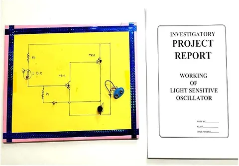
Light Sensitive Oscillator Physics Working Model Educational Investigatory Project
Code B0C3H8L1X3
- Paid for and delivered by Amazon. The current price and the delivery date for your PIN code are shown there.
- Sold by Gurukul Technicals Institute, Delhi.
- Need a different topic, a custom version or a school order? Ask on WhatsApp.
In this project guide
Ready-made model
About this model
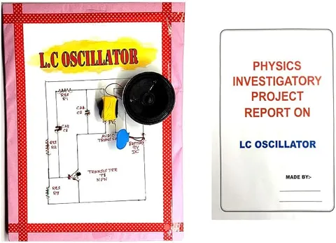
This light sensitive oscillator is a circuit whose oscillation frequency changes with the amount of light falling on its sensor. In the usual form of this project the output is a tone, so brighter or dimmer light can actually be heard as a higher or lower pitch.
How it works
The science behind it
The idea the model demonstrates, in words you can use in your report and when you explain it.
An oscillator is a circuit that produces a repeating signal on its own, switching between high and low many times a second. A common choice is the 555 timer in astable mode, whose frequency is f ≈ 1.44 / ((R1 + 2R2) × C). The frequency depends on the resistors and the capacitor: more resistance means the capacitor charges and discharges more slowly, so the frequency falls. In a light sensitive oscillator, one of these resistors is replaced by a light dependent resistor (LDR). In bright light the LDR's resistance is low, so the frequency is high and the tone sounds sharp; in dim light its resistance rises, the frequency falls and the tone drops. The circuit therefore converts light intensity into frequency. Devices built on this idea have been used as light probes that let visually impaired people hear whether a lamp is on, and as simple light meters.
Make it yourself
Make a light sensitive tone oscillator yourself
Build your own version from scratch, or use the steps to understand how the ready-made model is put together before you present it.
What you need 10
Step by step 8 steps
- Wire the 555's supply
Pin 1 to negative, pins 4 and 8 to positive, and the 0.01 µF from pin 5 to negative.
Fit R1, one 1 kΩ resistor, from pin 8 to pin 7.
In place of R2, connect the LDR in series with the second 1 kΩ resistor from pin 7 to pins 2 and 6, which are joined. The fixed 1 kΩ stops the pitch going too high in very bright light.
Connect the 0.1 µF capacitor from pins 2 and 6 to negative.
Connect pin 3 through the 100 Ω resistor and the 10 µF capacitor (long leg towards pin 3) to the speaker, and the speaker's other terminal to negative.
- Switch on
In room light you should hear a steady tone. Cup your hand over the LDR and the pitch drops; shine the torch on it and the pitch rises.
In a dark room, fix the torch at one end of the ruler and read the frequency with the LDR at 10, 20, 30, 40 and 50 cm.
With the LDR taken out of the circuit, measure its resistance at the same distances and check your readings against f ≈ 1.44 / ((R1 + 2R2) × C).
Read this first
Safety first
Go through these points before you build or switch anything on. Younger students should do this with an adult.
- Keep the tone at a comfortable level and never hold the speaker against your ear.
- Fit the 555 with its notch the right way and the 10 µF capacitor with its long leg towards pin 3.
- Use the soldering iron only with an adult and rest it in its stand.
- Use a battery torch rather than a hot halogen lamp for the distance tests, so nothing near the board overheats.
Troubleshooting
If something does not work
The usual problems with this model and how to fix them. Open a problem to see the fix.
The tone does not change when the light changes
You may have used an active buzzer, which makes its own fixed tone. Use a plain speaker or a passive piezo disc, and check that the LDR really is in the R2 position.
There is no sound at all
Check the 555's notch, that pin 4 goes to positive, that the 10 µF capacitor faces the right way, and that the battery is good.
In the dark the speaker only clicks slowly
The LDR's resistance is now so high that the oscillator runs very slowly. Put a 100 kΩ resistor across the LDR to set the lowest pitch, or use a smaller capacitor to raise every pitch.
The readings change when I lean over the circuit
Your shadow, or room light, is changing the light on the LDR. Take readings in a dark room with only the torch on, and stand behind the torch.
Exhibition day
How to present it
A running order for the exhibition table or the practical, step by step.
Move your hand slowly over the sensor and show how the tone, or the blink rate if your model uses an LED, changes.
Explain how resistance controls frequency, using the 555 astable formula.
Compare the output in room light, under a torch and in shade.
Mention practical uses such as audible light meters for visually impaired people.
Practice
Viva questions
Practice questions on this model, with short answers. Try each one aloud before you open the answer.
What is an oscillator?
A circuit that produces a continuous repeating signal without any input signal, using energy from its power supply.
What happens to the frequency when more light falls on the LDR?
The LDR's resistance falls, so the frequency rises and the pitch gets higher.
What is the frequency formula for a 555 astable circuit?
f ≈ 1.44 / ((R1 + 2R2) × C).
What does astable mean?
It has no stable state, so the output keeps switching between high and low on its own.
Project file
Project file outline
The headings of the project file, in order. Give each heading its own section and write it in your own words.
Free ebook: Writing a Science Project FileContents
- Aim: to show that the frequency of an oscillator changes with the light falling on an LDR
- Introduction: what an oscillator is and where oscillators are used
- Theory: the 555 timer in astable mode and f ≈ 1.44 / ((R1 + 2R2) × C)
- Photoconductivity: why the LDR's resistance falls in light
- Circuit diagram and construction
- Observations: distance from the torch, LDR resistance and measured frequency
- Graph of frequency against distance and comparison with the formula
- Applications: light meters, sound-based aids for the visually impaired and light-controlled toys
- Precautions, sources of error and conclusion
Buying checklist
Before you buy
What to check before you order the model, and what to do when it arrives.
1Before you order
- Check that a 555 timer project suits your class level, and be ready to explain the frequency formula.
- Read the listing to see what kind of output it gives, a tone, a light or both, and what powers it.
- Practise a demonstration that works in a bright hall, such as covering the sensor with your hand or a cup.
- Keep the box so the sensor and speaker leads are not bent on the way.
- Check the delivery date for your PIN code on the marketplace, and order well before the exhibition or practical.
2When it arrives
- Test it in a dark corner and under a lamp as soon as it arrives, as exhibition halls are bright and noisy.
Next steps
Take it further
Ways to turn this model into a bigger investigation or a stronger exhibition entry.
Calibrate the pitch against a phone light meter app and turn the oscillator into a light meter you can hear.
Replace the LDR with a thermistor and turn the circuit into a temperature-to-pitch converter.
Plot frequency against 1 / distance² and discuss why the line is not perfectly straight.
Audience
Who it suits
Class 10 to 12 students and electronics hobbyists looking for an unusual investigatory project on sensors and oscillators.
- ClassClass 10 to 12
- SubjectPhysics
- TypeReady-made model
Free to read
Free ebooks for this topic
Free PDF ebooks from Gurukul Technicals Institute on the science, the making and the presenting of projects like this one.
- Free PDF ebook
Physics Working Models Explained
Twenty classic models, how each works and how to make it
- Free PDF ebook
Investigatory Projects for Class 11 and 12
Topics, method and report structure for physics, chemistry and biology
- Free PDF ebook
Your Science Exhibition Guide
Choose a project, build it, present it and answer the judges with confidence
- Free PDF ebook
Writing a Science Project File
How to write the report, from the cover page to the bibliography