- Physics
- Ready-made model
- Class 10 to 12
- Printed report included
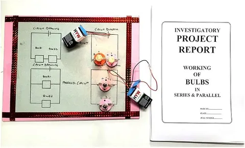
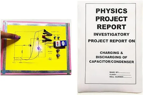
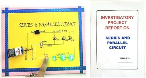
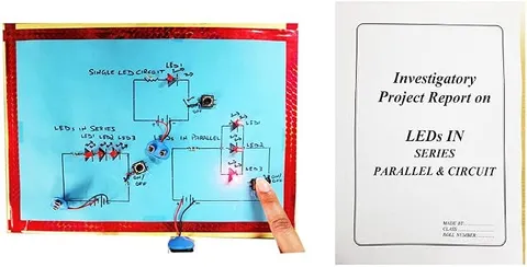
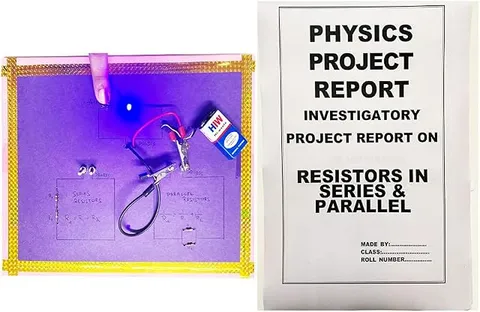
Series and Parallel Resistance Readymade Physics Working Investigatory Project & Model for School & College with Blue Indicator LED Light (Printed Report Included)
Code B099QYG4SB
- Paid for and delivered by Amazon. The current price and the delivery date for your PIN code are shown there.
- Sold by Gurukul Technicals Institute, Delhi.
- Need a different topic, a custom version or a school order? Ask on WhatsApp.
In this project guide
Ready-made model
About this model
This ready-made model compares resistors connected in series and in parallel, so students can see how the arrangement changes the current in a circuit. The listing mentions a blue indicator LED and says a printed report is included. It is a hands-on way to verify the resistance formulas from the electricity chapter.
How it works
The science behind it
The idea the model demonstrates, in words you can use in your report and when you explain it.
Resistance is the opposition a conductor offers to current, and by Ohm's law V = IR. When resistors are joined end to end in series, the same current flows through each, and the total resistance is the sum: Rs = R1 + R2 + R3. When they are joined across the same two points in parallel, each gets the same voltage, and the total is given by 1/Rp = 1/R1 + 1/R2 + 1/R3, which is always less than the smallest resistor. For two 10 Ω resistors, series gives 20 Ω and parallel gives 5 Ω. So with the same battery, the parallel arrangement draws more current, and an indicator in the circuit can glow brighter. Old Diwali bulb strings show series wiring well: if one bulb failed, the whole string went dark, while the lights in your house stay on independently because they are in parallel.
Make it yourself
Make a series and parallel resistance model yourself
Build your own version from scratch, or use the steps to understand how the ready-made model is put together before you present it.
What you need 8
Step by step 8 steps
Measure each resistor with the multimeter and write down its value; real values differ slightly from the colour code.
Build the series arm by joining three 1 kΩ resistors end to end.
Build the parallel arm by joining three 1 kΩ resistors side by side between two common points.
Measure the total resistance of each arm and compare with Rs = R1 + R2 + R3 and 1/Rp = 1/R1 + 1/R2 + 1/R3.
Connect battery positive to the middle pin of the SPDT switch and each outer pin to one arm. Join the far ends of both arms, then go through the 220 Ω resistor to the LED's long leg, and from its short leg back to negative.
Switch to the series arm and note the LED's brightness, then switch to parallel. The LED glows brighter, because the total resistance is smaller and more current flows.
Put the multimeter in series on its mA range to measure the current in each position, and check it with I = V / R, taking V as the battery voltage minus the voltage across the LED and R as the arm's resistance plus 220 Ω.
Fix everything on the base, label 'series' and 'parallel' with the measured values, and draw both circuit diagrams.
Read this first
Safety first
Go through these points before you build or switch anything on. Younger students should do this with an adult.
- Always keep the 220 Ω resistor in series with the LED; it keeps the LED current safe even if a stray wire shorts out an arm.
- Use only the 9 V battery, and check the wiring before connecting it.
- To measure current, put the multimeter in series on the correct range; placed across the battery on the current range it can blow the meter's fuse.
- Solder only with adult supervision.
Troubleshooting
If something does not work
The usual problems with this model and how to fix them. Open a problem to see the fix.
The LED looks equally bright in both positions
The switch may be wired wrongly. Measure each arm's resistance and check that the switch really changes between them.
The LED does not light in the series position
The current is small, so it may be very dim; look at it in shade. Also check every joint, because one break stops the whole series arm.
The measured total does not match the formula exactly
Resistors have a tolerance (often 5%), and the meter leads add a little resistance. Use your measured values in the formula and the agreement will be close.
The multimeter shows nothing on the current range
The red probe may be in the wrong socket, or the meter's internal fuse may have blown; ask your teacher to check it.
Exhibition day
How to present it
A running order for the exhibition table or the practical, step by step.
Measure each resistor with a multimeter first, then predict the series and parallel totals before switching on.
Show how the LED brightness changes between the two arrangements and link it to the current.
Write both formulas on a chart with one worked example using your actual resistor values.
If your model allows, take out one resistor in each arrangement to show that series breaks the circuit and parallel does not.
Practice
Viva questions
Practice questions on this model, with short answers. Try each one aloud before you open the answer.
What is the equivalent resistance of resistors in series?
It is the sum of the individual resistances: Rs = R1 + R2 + R3.
Why is the equivalent resistance in parallel less than the smallest resistance?
Each extra parallel path gives the current another route, so the total opposition to current decreases.
Which quantity is the same in a series circuit, and which in a parallel circuit?
Current is the same through all resistors in series, while voltage is the same across all resistors in parallel.
State Ohm's law.
At constant temperature, the current through a conductor is directly proportional to the potential difference across it, so V = IR.
Project file
Project file outline
The headings of the project file, in order. Give each heading its own section and write it in your own words.
The listing includes a printed project report: use this outline to check that your own file covers every part.
Free ebook: Writing a Science Project FileContents
- Aim: to verify the laws of combination of resistances in series and in parallel
- Introduction: resistance and Ohm's law
- Materials and circuit diagrams for both arrangements
- Theory: Rs = R1 + R2 + R3 and 1/Rp = 1/R1 + 1/R2 + 1/R3
- Procedure: measuring each arm and switching between them
- Observation table: measured and calculated resistance, current and LED brightness
- Calculations and percentage difference
- Result and conclusion
- Precautions and sources of error
Buying checklist
Before you buy
What to check before you order the model, and what to do when it arrives.
1Before you order
- The listing says a printed report is included; check it covers your syllabus and fill in your own readings.
- Check whether a battery is included, and keep a fresh 9 V spare.
- Arrange a multimeter if the listing does not mention one, so you can take real readings for the table.
- Keep the box to carry the model without bending the switch.
- Check the delivery date for your PIN code on the marketplace, and order well before the exhibition or practical.
- Practise explaining it. Judges ask what the model shows and why; knowing the science matters as much as the model. The viva questions above are a good place to start.
2When it arrives
- Test both positions on arrival and a few days before your practical, noting the LED's brightness in each.
Next steps
Take it further
Ways to turn this model into a bigger investigation or a stronger exhibition entry.
Add a mixed series-parallel combination and calculate its total before measuring it.
Use a light-meter app on a phone to compare the LED's brightness in numbers.
Plot the current against the number of resistors in series and in parallel.
Audience
Who it suits
Suits Class 10 and Class 12 physics projects on electricity and current electricity, and practical exam revision.
- ClassClass 10 to 12
- SubjectPhysics
- TypeReady-made model
- Project reportPrinted report included
Free to read
Free ebooks for this topic
Free PDF ebooks from Gurukul Technicals Institute on the science, the making and the presenting of projects like this one.
- Free PDF ebook
Electricity and Magnetism Experiments
Hands-on experiments with cells, wires, bulbs and magnets
- Free PDF ebook
Physics Working Models Explained
Twenty classic models, how each works and how to make it
- Free PDF ebook
Investigatory Projects for Class 11 and 12
Topics, method and report structure for physics, chemistry and biology
- Free PDF ebook
Your Science Exhibition Guide
Choose a project, build it, present it and answer the judges with confidence