- Physics
- Ready-made model
- Class 10 to 12
Series and Parallel Circuit Physics Investigatory Project Model Engineering College & Science Teaching Aid
Code B0DMKZB23J
- Paid for and delivered by Amazon. The current price and the delivery date for your PIN code are shown there.
- Sold by Gurukul Technicals Institute, Delhi.
- Need a different topic, a custom version or a school order? Ask on WhatsApp.
In this project guide
Ready-made model
About this model
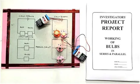
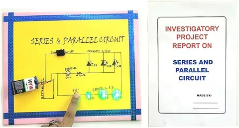
This investigatory project model compares series and parallel circuits, showing how the same components behave differently when connected in two ways. It is one of the most useful models for understanding why homes are wired in parallel. It suits Class 10 physics projects on electricity, with enough depth for Class 12 and teaching labs.
How it works
The science behind it
The idea the model demonstrates, in words you can use in your report and when you explain it.
In a series circuit the components are connected end to end, so the same current flows through each one, and the supply voltage is shared between them. The total resistance is the sum: R = R1 + R2 + R3. In a parallel circuit each component is connected directly across the supply, so each gets the full voltage, and the current divides between the branches. The total resistance is found from 1/R = 1/R1 + 1/R2 + 1/R3, and it is always less than the smallest branch resistance. For two 10 Ω resistors, series gives 20 Ω and parallel gives 5 Ω. If one bulb in a series circuit fuses, the path breaks and every bulb goes off; in parallel the others keep glowing. That is why the lights and fans in an Indian home are in parallel, each with its own switch, while some cheap festival light strings go dark when a single bulb fails.
Make it yourself
Make a series and parallel circuit board yourself
Build your own version from scratch, or use the steps to understand how the ready-made model is put together before you present it.
What you need 8
Step by step 8 steps
Divide the board into two halves labelled 'Series' and 'Parallel', each with its own switch.
On the series side, wire three bulbs end to end in a single loop with the switch.
On the parallel side, wire three bulbs so each holder connects directly across the two supply wires.
Switch each circuit on in turn and compare: the series bulbs glow dimly and the parallel bulbs brightly.
Unscrew one bulb on each side: all the series bulbs go out, but the other parallel bulbs stay lit.
Measure the voltage across each bulb and the current at different points in both circuits, and record them in a table.
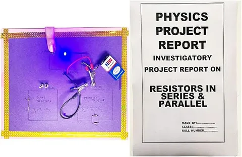
Disconnect the cells, put the three resistors in place of the bulbs, measure the total resistance in series and in parallel, and compare with the formulas.
Add a card showing how the lights and fans in a house are wired in parallel.
Read this first
Safety first
Go through these points before you build or switch anything on. Younger students should do this with an adult.
- Use only the cells; never connect this board to a socket or to house wiring.
- Never connect the multimeter on its current range straight across the cells; that is a short circuit and can blow the meter's fuse.
- Bulbs get hot, so switch off before unscrewing them.
- Do not leave the parallel side on for long; it draws a lot of current and drains the cells.
Troubleshooting
If something does not work
The usual problems with this model and how to fix them. Open a problem to see the fix.
None of the series bulbs light
One bulb is loose or fused, which breaks the whole loop. Tighten each one and test them one at a time.
The parallel bulbs are dimmer than expected
The cells may be weak, or the wires long and thin. Use fresh cells and shorter, thicker wires.
The meter reads zero current
The red probe may be in the wrong socket for current, or the meter's fuse has blown. Check the socket and the range.
Resistance readings do not match the formula
Measure with the cells disconnected, and remember that resistors are only accurate to within a few percent.
Exhibition day
How to present it
A running order for the exhibition table or the practical, step by step.
Remove or switch off one bulb in each circuit to show the key difference between series and parallel.
Compare the brightness of the bulbs in series and in parallel and explain it using V = IR.
Write both resistance formulas on the chart with one worked example.
Link the model to the wiring of your own house to show why it matters.
Practice
Viva questions
Practice questions on this model, with short answers. Try each one aloud before you open the answer.
What remains the same in a series circuit?
The current is the same through every component in a series circuit.
What remains the same in a parallel circuit?
The potential difference across each branch is the same and equal to the supply voltage.
Why are household appliances connected in parallel?
Each appliance gets the full mains voltage, can be switched independently and keeps working even if another one fails.
What is the equivalent resistance of two 10 Ω resistors in parallel?
5 Ω, since 1/R = 1/10 + 1/10 = 2/10.
Project file
Project file outline
The headings of the project file, in order. Give each heading its own section and write it in your own words.
Free ebook: Writing a Science Project FileContents
- Aim: to compare series and parallel connections of the same components
- Current, voltage, resistance and Ohm's law
- Rules for current, voltage and resistance in a series circuit
- Rules for current, voltage and resistance in a parallel circuit
- Circuit diagrams of the model
- Observation tables: bulb brightness, voltages, currents and resistance
- Why houses are wired in parallel
- Precautions, errors such as the cells running down, and conclusion
Buying checklist
Before you buy
What to check before you order the model, and what to do when it arrives.
1Before you order
- Check the class level in the listing and ask your teacher whether it is for Class 10 electricity or a higher class.
- See whether the listing mentions bulbs, LEDs or batteries; buy fresh cells if batteries are not mentioned.
- Keep the box for carrying it safely.
- Check the delivery date for your PIN code on the marketplace, and order well before the exhibition or practical.
- Practise explaining it. Judges ask what the model shows and why; knowing the science matters as much as the model. The viva questions above are a good place to start.
2When it arrives
- When it arrives, switch on each circuit and check every bulb or LED, and keep spare bulbs if the model uses them.
Next steps
Take it further
Ways to turn this model into a bigger investigation or a stronger exhibition entry.
Build a combination circuit (two bulbs in parallel, in series with a third) and predict the readings before measuring.
Plot a V-I graph for one bulb and show that its resistance rises as the filament heats up.
Calculate the power used by each bulb in series and in parallel from your readings.
Audience
Who it suits
Class 10 physics projects on electricity, as well as Class 6 to 8 exhibitions and teaching labs.
- ClassClass 10 to 12
- SubjectPhysics
- TypeReady-made model
Free to read
Free ebooks for this topic
Free PDF ebooks from Gurukul Technicals Institute on the science, the making and the presenting of projects like this one.
- Free PDF ebook
Electricity and Magnetism Experiments
Hands-on experiments with cells, wires, bulbs and magnets
- Free PDF ebook
Physics Working Models Explained
Twenty classic models, how each works and how to make it
- Free PDF ebook
Investigatory Projects for Class 11 and 12
Topics, method and report structure for physics, chemistry and biology
- Free PDF ebook
Your Science Exhibition Guide
Choose a project, build it, present it and answer the judges with confidence