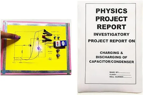
- Physics
- Ready-made model
- Class 10 to 12
- Printed report included
Capacitor In Series And Parallel Readymade Physics Working Project & Model For School & College (With Printed Report), Clear
Code B099QZ3XSX
- Paid for and delivered by Amazon. The current price and the delivery date for your PIN code are shown there.
- Sold by Gurukul Technicals Institute, Delhi.
- Need a different topic, a custom version or a school order? Ask on WhatsApp.
In this project guide
Ready-made model
About this model
A readymade physics working model that shows how capacitors behave when joined in series and in parallel. It helps Class 12 students see that capacitors combine the opposite way to resistors, and the listing says a printed report is included.
How it works
The science behind it
The idea the model demonstrates, in words you can use in your report and when you explain it.
A capacitor stores electric charge on two conducting plates separated by an insulator. The charge it holds is Q = CV, where C is its capacitance in farads, and the energy stored is U = ½CV². When capacitors are joined in parallel, each gets the same voltage, the charges add up, and the total capacitance is the sum: C = C1 + C2 + C3. When they are joined in series, each carries the same charge, the voltages add up, and the total follows 1/C = 1/C1 + 1/C2 + 1/C3, so the result is smaller than the smallest capacitor. For example, two 10 µF capacitors give 20 µF in parallel but only 5 µF in series. Resistors behave the opposite way. Parallel groups store more charge, while series groups can handle a higher total voltage. The capacitor an electrician replaces when a ceiling fan starts running slowly is an everyday example in Indian homes.
Make it yourself
Make a capacitors in series and parallel board yourself
Build your own version from scratch, or use the steps to understand how the ready-made model is put together before you present it.
What you need 9
Step by step 8 steps
Mount the three capacitors in a row with a terminal at each lead, and mark + and − clearly; the stripe on the capacitor's side marks the negative lead.
- Wire the switch
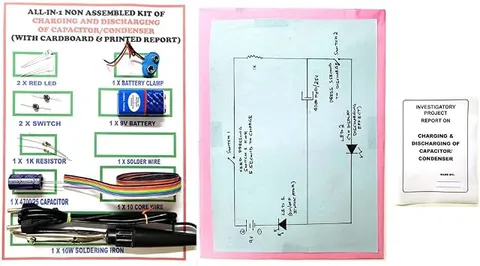
Its middle pin goes to the + end of the capacitor group. The CHARGE side goes to battery positive through the 100 Ω resistor; the DISCHARGE side goes through the 1 kΩ resistor and the LED (long leg towards the capacitors) to negative. The − end of the group goes to battery negative.
- Try one capacitor first
Charge it for five seconds, flip to DISCHARGE and time how long the LED glows.
- Parallel
Link all the + terminals together and all the − terminals together, and repeat. The LED glows about three times as long.
- Series
Link the − of the first capacitor to the + of the second and the − of the second to the + of the third, using the first + and the last − as the ends. Repeat: the glow lasts about a third as long.
Disconnect each arrangement, discharge it, and measure its capacitance with the multimeter. Compare with C = C1 + C2 + C3 for parallel and 1/C = 1/C1 + 1/C2 + 1/C3 for series.
Charge the series group and measure the voltage across each capacitor: each holds about a third of the battery's voltage.
Record all the results in a table.
Read this first
Safety first
Go through these points before you build or switch anything on. Younger students should do this with an adult.
- Fit every electrolytic capacitor the right way round, + towards battery positive; a reversed one can heat up, bulge or burst.
- Use capacitors rated well above the battery's voltage, such as 25 V for a 9 V battery.
- Discharge the capacitors through the LED circuit before rewiring or measuring, never by touching their leads together with a screwdriver, which sparks and can damage them.
- Use only the battery; never connect this board to an adapter or the mains.
Troubleshooting
If something does not work
The usual problems with this model and how to fix them. Open a problem to see the fix.
The LED flashes only for an instant, even in parallel
The capacitors may not be fully charged, a link may be loose, or the discharge resistor may be too small. Charge for longer and check every link.
The LED does not light at all on discharge
The LED is probably facing the wrong way. Its long leg must face the capacitors' + side.
The measured capacitance differs from the printed value
Electrolytic capacitors often have a tolerance of ±20%, so this is normal. Use your measured values in the calculations.
A capacitor's top is bulging
It has been reversed or over-voltaged. Stop using it at once and replace it.
Exhibition day
How to present it
A running order for the exhibition table or the practical, step by step.
Read the values of the capacitors on your model, work out the series and parallel totals, and display both results.
Explain that capacitors combine the opposite way to resistors, using a side-by-side formula card.
Point out which quantity is shared in each case: the same charge in series, the same voltage in parallel.
Mention that capacitors can hold charge after the supply is removed, so they are discharged before handling.
Practice
Viva questions
Practice questions on this model, with short answers. Try each one aloud before you open the answer.
What is the effective capacitance of two 10 µF capacitors in series?
It is 5 µF, because 1/C = 1/10 + 1/10 = 1/5.
Which quantity is the same for capacitors connected in parallel?
The potential difference across each capacitor is the same in a parallel combination.
Why is a series combination smaller than the smallest capacitor?
Adding the reciprocals gives a total 1/C larger than any single 1/C, so the combined C is smaller than any one capacitor.
What is the SI unit of capacitance?
The farad (F), which is one coulomb per volt; practical capacitors are usually measured in microfarads.
Project file
Project file outline
The headings of the project file, in order. Give each heading its own section and write it in your own words.
The listing includes a printed project report: use this outline to check that your own file covers every part.
Free ebook: Writing a Science Project FileContents
- Aim: to study capacitors joined in series and in parallel
- Theory: capacitance, Q = CV and stored energy U = ½CV²
- Derivation of the formulas for series and parallel combinations
- Circuit diagram of the charge and discharge board
- Observations: measured capacitance and LED glow time for one capacitor, series and parallel
- Comparison with the way resistors combine
- Precautions with electrolytic capacitors
- Uses: camera flashes, power supply smoothing and timing circuits
- Conclusion and bibliography
Buying checklist
Before you buy
What to check before you order the model, and what to do when it arrives.
1Before you order
- Check that capacitor combinations are in your syllabus (electrostatics) and what readings your teacher expects.
- The listing mentions a printed report; note the values printed on the model's capacitors so you can do your own calculations.
- Keep a spare battery and the box for transport.
- Check the delivery date for your PIN code on the marketplace, and order well before the exhibition or practical.
- Practise explaining it. Judges ask what the model shows and why; knowing the science matters as much as the model. The viva questions above are a good place to start.
2When it arrives
- Test it as soon as it arrives and again a few days before the exhibition.
Next steps
Take it further
Ways to turn this model into a bigger investigation or a stronger exhibition entry.
Use a 10 kΩ discharge resistor (a time constant of about 10 s with 1000 µF), read the voltage every few seconds, and plot the discharge curve to find the time constant.
Calculate the energy stored at 9 V in each arrangement and relate it to how long the LED glows.
Try a mixed arrangement, two in series with one in parallel, and predict its capacitance before measuring it.
Audience
Who it suits
Suits Class 12 physics practicals and investigatory projects on electrostatics, and diploma electronics students.
- ClassClass 10 to 12
- SubjectPhysics
- TypeReady-made model
- Project reportPrinted report included
Free to read
Free ebooks for this topic
Free PDF ebooks from Gurukul Technicals Institute on the science, the making and the presenting of projects like this one.
- Free PDF ebook
Physics Working Models Explained
Twenty classic models, how each works and how to make it
- Free PDF ebook
Your Science Exhibition Guide
Choose a project, build it, present it and answer the judges with confidence
- Free PDF ebook
Writing a Science Project File
How to write the report, from the cover page to the bibliography
- Free PDF ebook
Viva Questions for Science Projects
How to answer examiner questions, with sample questions for popular projects