
Hardware & Networking
Basic electronics
How circuits work and how to read them: resistors, diodes, capacitors, transistors, the multimeter, the breadboard and safe soldering.
Suits: Students from class 8 and hobbyists
Duration, fees and batch timings are quoted by the head office or your centre.
The study book of this course
- Basic Electronics
- Lessons
- 10
- Practice questions
- 40
- Free ebooks
- 0
About the course
What the basic electronics course is about
Electronics begins with understanding what current, voltage and resistance do, and learning to read a circuit diagram. The course covers the common components one by one and what each does in a circuit.
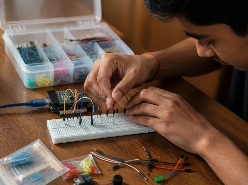
The student then learns to measure with a multimeter, build on a breadboard, solder neatly and find a fault, always with electrical safety first. It goes beyond the robotics classes’ electronics basics into power supplies, transistors and timers.
What you will practise
Drawn from the lessons of the study books below.
- 01
Follow the safety rules for electricity, batteries and soldering
- 02
Read circuit symbols and diagrams
- 03
Calculate with Ohm’s law, power and LED series resistors
- 04
Identify resistors, capacitors, diodes, LEDs and transistors
- 05
Measure voltage, current and resistance with a multimeter
- 06
Build a circuit on a breadboard, solder it and trace a fault
What you will learn
10 lessons, 30 exercises
Every lesson of the study book that comes with this course in the student portal, with the key points of each lesson and exercises to try. Your centre gives you the syllabus, the duration and the fee.
Study book
Basic Electronics
Learn how electricity works and how to stay safe, how to read circuit diagrams, and how resistors, capacitors, diodes, transistors and ICs behave, then practise with a multimeter, breadboard and a small project.
1Electricity and Staying Safe4 min read · 4 key points · 3 exercises
Key points
- Voltage pushes, current flows, and resistance opposes the flow.
- V = I × R and P = V × I are the two formulas used most often.
- Experiment only with batteries and low-voltage supplies, never with the mains.
- A short circuit gives a large current that can burn wires and batteries.
Try this
- A 12 V supply drives 0.5 A through a lamp. Calculate its power in watts, and the energy in watt-hours if it stays on for 4 hours.
- List five conductors and five insulators found in your home or classroom.
- Write a "safety card" of five rules for your lab bench and stick it near your work table.
2AC, DC and Mains Safety4 min read · 4 key points · 3 exercises
Key points
- DC flows one way; AC reverses direction, and Indian mains is about 230 V at 50 Hz.
- Transformers make AC convenient for long-distance power transmission.
- The earth wire, fuse, MCB and RCCB each protect against faults and shocks.
- Beginners should never open or wire anything connected to the mains.
Try this
- Make a two-column table of ten things around you and write whether each runs on AC, DC or both (with an adapter).
- Look at a plug top at home (without opening it) and identify the three pins. Note which is the longest.
- Find the MCB or fuse box in your house with an adult. Write down what is labelled and do not touch the switches.
3Reading Circuit Diagrams4 min read · 4 key points · 3 exercises
Key points
- A schematic shows connections with standard symbols, not the real shape of parts.
- A dot at a crossing means a joint; no dot means the wires only pass.
- Parts are labelled with a name (R1, C1, D1) and a value.
- k, M, m and µ are prefixes you must convert before using formulas.
Try this
- Draw the schematic of a battery, switch, resistor and LED in series, labelling every part.
- Convert: 2.2 kΩ to ohms, 47 mA to amperes, 0.5 A to milliamperes, 100 µF to farads.
- Cut a circuit diagram from a magazine or textbook and write a sentence for each symbol you recognise.
4Resistors, Capacitors and Inductors4 min read · 4 key points · 3 exercises
Key points
- Resistor colour bands give two digits and a multiplier.
- Series resistances add; parallel ones combine to a smaller value.
- A capacitor stores charge; its timing is T = R × C; electrolytics have polarity.
- An inductor stores energy in a magnetic field and fights sudden current changes.
Try this
- Read these resistors: orange orange brown; green blue red; brown grey orange.
- Calculate the total of 1 kΩ and 2.2 kΩ in series, and the voltage across the 2.2 kΩ when 6 V is applied across the pair.
- Find a capacitor (from old electronics, with an adult) and note its value and whether it has a polarity mark.
5Diodes and LEDs4 min read · 4 key points · 3 exercises
Key points
- A diode conducts one way and drops about 0.7 V when it does.
- An LED needs a series resistor: R = (supply - LED voltage) / current.
- The longer LED leg is the anode (+).
- Always check the resistor wattage with P = I² × R.
Try this
- Calculate the resistor for a 6 V supply, a green LED of 2.2 V and 10 mA. Choose the nearest standard value.
- Build the circuit on a breadboard with a 220 Ω resistor and see what happens when you reverse the LED. Then straighten it again.
- Make a table of LED colours, their typical voltage drop (from your lab or textbook) and a suitable resistor for a 5 V supply.
6From Mains to a DC Supply4 min read · 4 key points · 3 exercises
Key points
- A power supply has four steps: transformer, rectifier, filter and regulator.
- A full-wave bridge rectifier uses four diodes and gives 100 pulses per second from 50 Hz mains.
- The peak of an AC supply is about 1.414 times its RMS value, minus diode drops.
- A linear regulator wastes (input - output) × current as heat.
Try this
- Draw a block diagram of a power supply with four boxes and write what each box does.
- A transformer gives 9 V RMS. Calculate its peak voltage, and the DC peak after a bridge rectifier (subtract 1.4 V).
- Calculate the heat loss in a regulator with 9 V in, 5 V out and 0.2 A load.
7Transistors as Switches4 min read · 4 key points · 3 exercises
Key points
- A transistor uses a small base current to control a larger collector current.
- The base resistor is (input - 0.7 V) divided by the wanted base current.
- Coils need a flyback diode across them to absorb the switch-off spike.
- A MOSFET switches with gate voltage and handles large currents efficiently.
Try this
- Calculate the base resistor for 5 V input, 0.7 V base-emitter drop, and 1.5 mA base current.
- Draw the complete schematic of an NPN switch driving a buzzer, labelling base, collector and emitter.
- Look at the datasheet or pack of a BC547 or similar transistor and write down the leg order and maximum collector current.
8ICs and the 555 Timer4 min read · 4 key points · 3 exercises
Key points
- An IC packs many components into one chip; pin 1 is next to a notch or dot.
- The 555 timer has monostable (one pulse) and astable (repeating) modes.
- Monostable time is T = 1.1 × R × C.
- Astable frequency is f = 1.44 / ((R1 + 2R2) × C).
Try this
- Calculate the pulse length for R = 47 kΩ and C = 100 µF in monostable mode.
- Pick R1, R2 and C values from your box to make the astable 555 blink slowly, and compute the frequency before building it.
- Draw the 555 chip from the top, with the notch at the top and the pin numbers 1 to 8 correctly placed.
9Multimeter, Breadboard and Soldering4 min read · 4 key points · 3 exercises
Key points
- Measure voltage in parallel and current in series; resistance with power off.
- The continuity beep test is a fast way to find broken wires and joints.
- On a breadboard, a short five-hole strip is connected; the centre gap isolates the two sides.
- A good solder joint is shiny and cone-shaped; always keep the hot iron in its stand.
Try this
- Use a multimeter to measure a fresh AA cell, and then a used one. Record both readings.
- Build a circuit on a breadboard with a battery, resistor and LED. Measure the voltage across the resistor and across the LED, and check that they add to the supply.
- Practise soldering (with supervision) on a scrap board and judge each joint as good or poor.
10Troubleshooting and a Small Project4 min read · 4 key points · 3 exercises
Key points
- Read the schematic and estimate values before building.
- Fault finding is systematic: look, check power, check connections, measure, split, change one thing.
- Most beginner faults are reversed parts and loose breadboard contacts.
- A potential divider with an LDR can control a transistor to make a night-light.
Try this
- Draw the night-light schematic and mark where you would measure voltage to check the divider.
- Introduce a deliberate fault (reverse the LED) on your breadboard circuit, then use the fault-finding steps to find it again.
- Write a one-page project report with the aim, parts list, circuit diagram, result and one improvement.
Glossary: 26 key terms of Basic Electronics
- Voltage
- The electrical push that drives current round a circuit, measured in volts (V).
- Current
- The flow of electric charge, measured in amperes (A).
- Resistance
- How much a part opposes current, measured in ohms (Ω).
- Ohm's law
- The rule V = I × R linking voltage, current and resistance.
- Power
- The rate of using energy, P = V × I, measured in watts (W).
- Circuit
- A complete path round which current can flow.
- Short circuit
- An accidental low-resistance path that lets a very large current flow.
- AC
- Alternating current, which reverses direction regularly; mains in India is about 230 V at 50 Hz.
- DC
- Direct current, which flows in one direction, as from a battery.
- Earth wire
- A safety wire that gives fault current a safe path to the ground.
- MCB
- Miniature circuit breaker, a resettable switch that trips on overload or short circuit.
- Schematic
- A circuit diagram that uses standard symbols to show connections.
- Resistor
- A part that limits current, with its value shown by coloured bands.
- Capacitor
- A part that stores electric charge, measured in farads.
- Inductor
- A coil that stores energy in a magnetic field, measured in henrys.
- Diode
- A part that lets current pass mainly in one direction.
- LED
- A light emitting diode, which glows when current passes through it the right way.
- Rectifier
- A circuit of diodes that turns AC into pulsing DC.
- Ripple
- The small leftover wave on a DC supply after smoothing.
- Regulator
- A part or circuit that holds a steady output voltage.
- Transistor
- A three-legged part that works as an electronic switch or amplifier.
- IC
- Integrated circuit, a chip holding many components in one package.
- 555 timer
- A popular 8-pin IC used to make pulses, delays and blinking signals.
- Multimeter
- A meter that measures voltage, current and resistance and tests continuity.
- Breadboard
- A solderless board for building temporary circuits.
- Continuity
- An unbroken low-resistance path, tested with the multimeter beep.
Practice and study material
Study books and timed practice tests in the student portal
Students sign in to read the study books lesson by lesson, print them, mark lessons as done and test themselves with timed practice tests, every answer explained.
- 1study book
- 10lessons
- 40practice questions
- 26glossary terms
How the practice tests work
- Fresh questions each time
Up to 20 questions are picked at random from the subject’s question bank.
- One minute per question
A timer counts down. When it reaches zero, your answers are sent automatically.
- Move around freely
Skip a question, flag it, and come back to change your answer before you submit.
- Learn from every answer
At the end you see the right answer and an explanation for each question.
- Read, print and keep track
Each study book has its lessons, key points, exercises and a glossary. Print a lesson, or mark it as done.
Your centre gives you your login when you enrol.
Try 3 practice questions
Real questions from this course’s question banks. Pick an answer to see the explanation.
Resistor bands yellow, violet, brown have a value of:
Show the answer
Answer: B. 470 Ω
4 and 7 give 47, and the brown multiplier adds one zero: 470 Ω.
A full-wave rectifier fed from 50 Hz mains produces ripple at:
Show the answer
Answer: D. 100 Hz
Both half cycles are used, so there are 100 pulses per second.
Where should a hot soldering iron be placed when not in use?
Show the answer
Answer: B. In its stand
The tip is very hot and must rest in its stand.
Careers
Careers this course leads towards
The kind of work these skills are used for. Each guide explains what the job involves, the skills it asks for and how to get started.
Robotics and electronics
Designing and building circuits, sensors and robots, and programming microcontrollers such as the Arduino.
Hardware and networking technician
Assembling and repairing computers, installing Windows and drivers, and setting up and fixing office networks.
Free calculators
Useful calculators
Free tools that go with this course. They work in your browser, on a phone or a computer.
Ohm’s law calculator
Find the voltage, current or resistance of a circuit from the other two (V = I × R).
Resistor colour code
Read the value of a resistor from its coloured bands.
LED resistor calculator
Find the series resistor an LED needs for your supply voltage.
How admission works
From your first question to your certificate.
The usual steps, at the head office in Delhi or at an authorised member centre.
- Who can join
- Students above 12 years of age.
- Where
- The Delhi head office and authorised member centres.
- Fees and timings
- On WhatsApp at +91 97116 99511, or by phone on 011 2721 1512.
- 1
Ask about the course
Call or WhatsApp the head office, or visit your nearest member centre. Ask for the duration, the fee and the batch timings in writing.
- 2
Fill the admission form
Admission forms are supplied by the head office to every centre.
- 3
Learn in class
Attend your batch at the centre, with the course material and study notes, and sign in to the student portal for the study books and practice tests.
- 4
Take the exam
The institute prefers written exams, taken in front of a teacher.
- 5
Receive your certificate
Students who pass get a Gurukul Technicals Institute certificate and marksheet. Employers can verify it with the head office.
Who can join the basic electronics course?
Students above 12 years of age can take admission, at the Delhi head office or at an authorised member centre. The course suits students from class 8 and hobbyists. Tell the head office or your centre what you already know, and they will suggest where to start.
How long is the course and what is the fee?
Duration, fees and batch timings depend on the course and the centre. Ask the head office or your nearest member centre, and get the details in writing before you pay.
Where are the classes?
At the head office in Delhi (A-10, Chief Commissioner Colony, opposite Rana Pratap Bagh) and at authorised member centres. Call or WhatsApp the head office to find the nearest centre.
What do I need to use the study books and practice tests?
A phone or a computer with an internet connection, and the login your centre gives you at enrolment. The student portal opens in an ordinary web browser, so there is nothing to install. Student login.
How do the practice tests work?
Sign in to the student portal and choose a subject. Each test picks up to 20 questions at random from that subject’s question bank and gives you one minute per question, with a timer that sends your answers automatically when it reaches zero. You can skip a question, flag it and come back before you submit, and at the end you see the right answer and an explanation for every question. This course has 40 practice questions across 1 subject, and you can take the tests as often as you like.
Is there an exam and a certificate?
Yes. The institute prefers written exams, taken in front of a teacher. Students who pass receive a Gurukul Technicals Institute certificate and marksheet.
How is a Gurukul Technicals Institute certificate verified?
On the verify certificate page, anyone can enter a certificate number and check it against the institute’s online register, which covers certificates issued through the portal. For older certificates, or if there is any doubt, send a copy to the head office by email or WhatsApp; the reply comes within 2 working days.
Ready to start the basic electronics course?
Ask the head office for the duration, the fee, the batch timings and your nearest member centre.