Head office, Rana Pratap Bagh, Delhi011 2721 1512+91 97116 99511

Robotics & Coding

Robotics for class 8 to 12

Advanced robotics with Arduino, line-follower robots and embedded systems.

Suits: Class 8 to 12

Batch timings and fees are shared on WhatsApp.
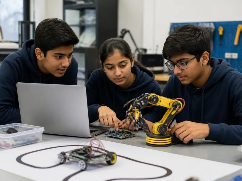
Three teenage students programming a robotic arm and a line-following robot from a laptop

2 study books in this course

  • Robotics and Electronics Basics
  • Arduino and Coding for Robots
Lessons
14
Practice questions
70
Free ebooks
13

About the course

About robotics for class 8 to 12

Students move from basic electronics to Arduino programming and embedded systems, and build an autonomous robot along the way.

Work starts on the breadboard with LEDs, resistors, transistors, the 555 timer and op-amps, moves into the Arduino IDE, digital and analog signals, ADC and serial communication, and ends with robots that follow lines and avoid obstacles. A 30-day robotics and embedded systems module is also run as a full course.

What they learn

From the robotics class page.

  1. 01

    Electronics on the breadboard: LEDs, resistors, transistors, the 555 timer and op-amps

  2. 02

    The Arduino IDE, digital and analog signals, ADC and serial communication

  3. 03

    Sensor calibration, and how robots follow lines and avoid obstacles

  4. 04

    Working from a circuit diagram to a finished, working project

What you will learn

2 subjects, 14 lessons

Every lesson of the study books that come with this course in the student portal, with the key points of each lesson and exercises to try. What students build in class is listed further down this page.

Subject 1 of 2

Robotics and Electronics Basics

Learn how electricity, circuits and electronic parts work, then use motors, sensors and batteries safely to understand how simple robots such as line followers and obstacle avoiders think and move.

  • 7 lessons
  • About 28 min of reading
  • 35 practice questions
  • 25 key terms
  1. 1Little Learners: What Is a Robot?4 min read · 5 key points · 3 exercises

    Key points

    • A robot is a machine that can do a job by itself.
    • A robot senses with sensors, thinks with a controller and moves with motors.
    • A battery gives electricity and has a plus end and a minus end.
    • Electricity flows only around a complete, round path called a circuit.
    • Never touch a wall socket, and play with batteries only with a grown-up.

    Try this

    1. Draw a robot and colour in its sensors (eyes), its controller (brain) and its motors (muscles), then tell a friend what each part does.
    2. With your teacher, connect a battery holder, a switch and a small bulb or LED module, and turn the switch on and off to make and break the circuit.
    3. With a grown-up, walk around your home and make a list of three things that run on batteries.
  2. 2Voltage, Current, Resistance and Ohm's Law4 min read · 5 key points · 3 exercises

    Key points

    • Voltage (volts) is the push, current (amperes) is the flow and resistance (ohms) opposes the flow.
    • Ohm's law is V = I × R, so I = V ÷ R and R = V ÷ I.
    • Convert mA to A and kΩ to Ω before you calculate.
    • Power is P = V × I, and every part has a maximum power rating.
    • Measure voltage across a part and current in series with it.

    Try this

    1. Use Ohm's law to find the current when 6 V is connected across a 300 Ω resistor, then check your answer of 20 mA with a multimeter at the centre.
    2. Measure the voltage of a new AA cell and of a used one with a multimeter and compare the readings.
    3. Make a table of five voltage and resistance pairs of your choice and calculate the current and the power for each.
  3. 3Series and Parallel Circuits on a Breadboard4 min read · 5 key points · 3 exercises

    Key points

    • A breadboard joins the five holes of each row on one side of the centre gap; the edge strips are power rails.
    • Series: one path, the same current everywhere, and voltages and resistances add.
    • Parallel: separate branches, the same voltage on each, currents add, and the total resistance is below the smallest branch.
    • Home wiring is parallel so each appliance works on its own.
    • Cells in series add their voltages.

    Try this

    1. On a breadboard, connect a 1 kΩ and a 2.2 kΩ resistor in series, calculate the total (3.2 kΩ), then measure it with a multimeter.
    2. Calculate the total resistance of two 470 Ω resistors in parallel (235 Ω) and check it with a multimeter.
    3. Build two LEDs, each with its own 220 Ω resistor, in parallel across a 5 V supply, then remove one LED and observe that the other keeps glowing.
  4. 4Electronic Components: From Resistors to Relays4 min read · 5 key points · 3 exercises

    Key points

    • Resistor bands give two digits, then the number of zeros, then the tolerance (gold is ±5%).
    • An LED needs a series resistor: R = (supply voltage − forward voltage) ÷ current.
    • A diode conducts one way only, and its stripe marks the cathode.
    • Electrolytic capacitors are polarised and need a voltage rating above the circuit voltage.
    • A transistor or a relay lets a small signal switch a bigger load.

    Try this

    1. Pick five resistors from the kit, read each colour code, and check your answers with a multimeter.
    2. Calculate the resistor for a red LED (about 2 V) on a 9 V battery at 15 mA, then build the circuit with the nearest standard value above your answer (470 Ω).
    3. Find the COM, NO and NC terminals on a relay module, then use the multimeter's continuity mode to see which pair is connected while the relay is off.
  5. 5Motors, Batteries and Power Safety4 min read · 5 key points · 3 exercises

    Key points

    • Reversing a DC motor's wires reverses its direction; voltage or PWM sets its speed.
    • A BO motor is a DC motor with a gearbox that trades speed for torque.
    • A servo turns to a commanded angle; a stepper moves in exact, fixed steps.
    • Motors are powered through a driver, never straight from a controller pin.
    • Never short a battery, never mix cells, and keep projects away from mains.

    Try this

    1. Connect a BO motor to a holder of two AA cells, note which way the wheel turns, then swap the wires and note the change.
    2. Read the labels of three different batteries at the centre and write down each one's voltage and, where shown, its capacity in mAh.
    3. Make a safety poster for your lab that lists the battery rules from this lesson.
  6. 6Sensors: IR, Ultrasonic, LDR and Touch4 min read · 5 key points · 3 exercises

    Key points

    • Digital sensors give HIGH or LOW; analog sensors give a smoothly changing voltage.
    • IR modules detect reflected infrared: white surfaces reflect it and black surfaces absorb it.
    • HC-SR04 distance = echo time × speed of sound ÷ 2.
    • An LDR's resistance falls in brighter light, and it is read through a voltage divider.
    • A capacitive touch module senses a finger and gives a digital output.

    Try this

    1. Hold an IR module over white paper and then over black tape, watch its indicator LED, and adjust the potentiometer until it switches cleanly between the two.
    2. Calculate the distance for echo times of 580 µs and 2,900 µs (about 10 cm and 50 cm).
    3. Measure an LDR's resistance with a multimeter in room light, under a torch and covered by your hand, and record the three readings.
  7. 7How Simple Robots Work: Line Followers and Obstacle Avoiders4 min read · 5 key points · 3 exercises

    Key points

    • A robot repeats a sense, think, act loop many times a second.
    • Differential drive steers by running the two wheels at different speeds or directions.
    • A two-sensor line follower turns towards whichever sensor sees the line.
    • An obstacle avoider stops, backs off and turns when the distance falls below a set limit.
    • Test motors and each sensor separately before running the whole robot.

    Try this

    1. On paper, draw a robot and a black line, and act out with a partner what the robot does in each of the four sensor cases.
    2. Mark a 20 cm line with tape, push a robot towards a wall by hand, and note when its ultrasonic reading falls below 20.
    3. Write your own rules, as steps, for a robot that stops when its touch sensor is pressed and starts again when it is pressed a second time.
Glossary: 25 key terms of Robotics and Electronics Basics
Ampere
The unit of electric current, written A, where 1 A equals 1000 mA.
Anode
The positive leg of a diode or LED, through which conventional current enters.
Breadboard
A reusable board with connected rows of holes for building circuits without soldering.
Capacitor
A component that stores electric charge, measured in farads.
Cathode
The negative leg of a diode or LED, marked by a stripe on a diode and by the shorter leg on an LED.
Circuit
A complete, closed path around which electric current can flow.
Current
The rate of flow of electric charge, measured in amperes.
Differential drive
A way of steering a robot by running its left and right wheels at different speeds or in different directions.
Diode
A component that lets current flow in one direction only.
LDR
A light-dependent resistor, whose resistance falls as the light on it gets brighter.
LED
A light-emitting diode, which glows when current flows from its anode to its cathode.
Motor driver
A circuit, such as the L298N, that supplies the large current a motor needs under the control of a small signal.
Ohm
The unit of resistance, written with the symbol Ω.
Ohm's law
The rule V = I × R that links voltage, current and resistance.
Parallel circuit
A circuit in which each part has its own branch across the same voltage.
Relay
A switch worked by an electromagnet, which lets a small current control a separate circuit.
Resistor
A component that limits the current in a circuit.
Sensor
A device that turns something in its surroundings, such as light or distance, into an electrical signal.
Series circuit
A circuit with a single path, in which the same current flows through every part.
Servo motor
A motor with built-in control that turns to and holds a commanded angle.
Short circuit
An accidental path of very low resistance that lets a dangerously large current flow.
Stepper motor
A motor that turns in fixed, equal steps so that its position can be set exactly.
Transistor
A semiconductor device that uses a small current to switch or amplify a larger one.
Ultrasonic sensor
A sensor that measures distance by timing the echo of sound too high-pitched for people to hear.
Voltage
The electrical push between two points, measured in volts.

Subject 2 of 2

Arduino and Coding for Robots

Program an Arduino Uno from your first blinking LED to a working robot: pins, the Arduino IDE, inputs and outputs, the Serial Monitor, variables, decisions, loops and functions, sensors, motor drivers, servos and debugging.

  • 7 lessons
  • About 25 min of reading
  • 35 practice questions
  • 25 key terms
  1. 1Meet the Arduino Uno and Its Pins4 min read · 5 key points · 3 exercises

    Key points

    • The Uno R3 uses the ATmega328P microcontroller at 16 MHz and works at 5 V.
    • It has 14 digital pins, 6 of them with PWM (marked ~), and 6 analog inputs, A0 to A5.
    • Keep pins 0 and 1 free for USB serial; pin 13 has the built-in LED.
    • Every part of a project must share a common GND.
    • A pin can supply only about 20 mA, so motors and relays need a driver.

    Try this

    1. On a real Uno, find the PWM pins (~), the analog pins, the GND pins, the 5V pin and the USB socket, and point them out to your partner.
    2. Draw a labelled diagram of the board on paper showing each group of pins and what it is used for.
    3. List three loads that need more than 20 mA and write down what you would use to switch each one.
  2. 2The Arduino IDE and Your First Sketch3 min read · 5 key points · 3 exercises

    Key points

    • A sketch is saved as a .ino file inside a folder of the same name.
    • Verify compiles the sketch; Upload compiles it and sends it to the board.
    • setup() runs once and loop() repeats for ever.
    • pinMode sets a pin's mode, digitalWrite sets it HIGH or LOW, and delay pauses in milliseconds.
    • Arduino code is case-sensitive, and each instruction ends with a semicolon.

    Try this

    1. Upload the Blink sketch, then change both delays to 200 and watch the LED blink faster.
    2. Wire an LED with a 220 Ω resistor to pin 8 and make it blink using a named constant for the pin.
    3. Make the LED flash a pattern: on for 200 ms, off for 200 ms, on for one second, off for one second.
  3. 3Buttons, digitalRead and the Serial Monitor3 min read · 5 key points · 3 exercises

    Key points

    • digitalRead returns HIGH or LOW.
    • A floating input reads at random; INPUT_PULLUP fixes this with a built-in resistor.
    • With INPUT_PULLUP and a button wired to GND, a pressed button reads LOW.
    • Serial.begin(9600) starts serial communication, and the Serial Monitor must use the same baud rate.
    • Serial.print and Serial.println let you see inside a running program.

    Try this

    1. Build the button-and-LED circuit and confirm the messages in the Serial Monitor.
    2. Change the sketch so that the LED is on when the button is not pressed and off while it is held.
    3. Write a sketch with Serial.begin(9600); in setup() and Serial.println(millis()); followed by delay(1000); in loop(), and watch the number grow by about 1000 each time.
  4. 4Variables, if/else and Loops4 min read · 5 key points · 3 exercises

    Key points

    • On the Uno R3 an int is 16 bits (−32,768 to 32,767); use long or unsigned long for bigger values.
    • == compares two values, while = assigns a value.
    • if, else if and else choose between actions, and && and || combine conditions.
    • for repeats a counted number of times; while repeats as long as a condition is true.
    • Use const for values, such as pin numbers, that never change.

    Try this

    1. Write a sketch that blinks an LED the number of times stored in a variable called count.
    2. Use if and else to print "Too close" when a variable called distance is below 20 and "Clear" otherwise, and test it with several values.
    3. Make running lights on four LEDs connected to pins 4 to 7, each with its own resistor, using a for loop.
  5. 5Analog Input, PWM Output and Functions3 min read · 5 key points · 3 exercises

    Key points

    • analogRead returns 0 to 1023 for 0 V to 5 V on the Uno.
    • analogWrite outputs PWM with a value from 0 to 255, only on the pins marked ~.
    • The duty cycle is the fraction of time a PWM signal is on.
    • map() rescales a value from one range to another.
    • Functions take parameters, can return a value and keep loop() short.

    Try this

    1. Connect a 10 kΩ potentiometer to A0 and print the readings while turning the knob from one end to the other.
    2. Make an LED on pin 9 fade up from 0 to 255 and back down again using two for loops and analogWrite.
    3. Write a function called isDark() that returns true when the reading from an LDR divider on A0 crosses a threshold you find by testing.
  6. 6Reading Sensors and Driving Motors with the L298N4 min read · 5 key points · 3 exercises

    Key points

    • pulseIn() measures how long the HC-SR04 Echo pin stays HIGH, in microseconds.
    • Distance in cm = duration × 0.0343 ÷ 2, and a result of 0 means no echo arrived in time.
    • The L298N's two H-bridges run two DC motors forwards or backwards from a separate battery.
    • IN1 and IN2 set the direction; analogWrite on ENA sets the speed.
    • The motor driver and the Arduino must share a common ground.

    Try this

    1. Wire the HC-SR04 and print distances to the Serial Monitor while moving your hand closer and further away, comparing the readings with a ruler.
    2. Connect one BO motor through the L298N and run the motorA() sketch, then change the speeds and timings.
    3. Add a second motor on ENB, IN3 and IN4 and write a motorB() function so that both wheels can be driven.
  7. 7The Servo Library and Debugging Your Robot4 min read · 5 key points · 3 exercises

    Key points

    • Include the library with #include <Servo.h>, create a Servo object, attach it to a pin and write an angle from 0 to 180.
    • On the Uno R3 the Servo library disables analogWrite on pins 9 and 10.
    • Power several servos, or a loaded servo, from a separate 5 V supply with a common ground.
    • Compile, upload and logic errors each need a different approach; read the first compile error first.
    • Use Serial.println to see what the board sees, and test one part at a time.

    Try this

    1. Upload the servo sketch, then change it to sweep smoothly from 0 to 180 degrees one degree at a time using a for loop.
    2. Delete a semicolon and misspell a variable on purpose, click Verify, and note the exact error messages the IDE shows.
    3. Mount the HC-SR04 on the servo and print the distance at 0, 90 and 180 degrees to find the direction with the most space.
Glossary: 25 key terms of Arduino and Coding for Robots
analogRead()
The function that reads the voltage on an analog pin and returns a number from 0 to 1023 on the Uno.
analogWrite()
The function that outputs a PWM signal with a value from 0 to 255 on a PWM pin.
Arduino IDE
The free program used to write, verify and upload Arduino sketches.
Baud rate
The speed of serial communication in bits per second, such as 9600.
Bootloader
A small program kept on the microcontroller that lets new sketches be uploaded over USB.
Bug
A mistake in a program or a circuit that makes it behave wrongly.
Compile
To translate a sketch's C++ code into machine code that the microcontroller can run.
Debugging
Finding and fixing the causes of errors in a program or a circuit.
digitalRead()
The function that returns HIGH or LOW from a digital input pin.
digitalWrite()
The function that sets a digital output pin HIGH or LOW.
Duty cycle
The fraction of each cycle for which a PWM signal stays on.
Floating input
An input pin connected to nothing, which gives random readings.
Function
A named block of code that can take parameters and return a value.
GND
Ground, the 0 V reference point that every part of a circuit must share.
H-bridge
A circuit of four switches that can drive a DC motor in either direction.
INPUT_PULLUP
A pin mode that switches on the microcontroller's built-in pull-up resistor.
Library
A ready-made collection of code, such as Servo, that adds features to a sketch.
loop()
The function that runs over and over after setup() has finished.
Microcontroller
A small computer on a single chip with its own processor, memory and input/output pins.
PWM
Pulse-width modulation, which switches a pin on and off rapidly to imitate an in-between voltage.
Serial Monitor
The IDE window that shows text sent by the board and can send text back to it.
setup()
The function that runs once when the board starts or is reset.
Sketch
An Arduino program, saved as a .ino file.
Upload
To send a compiled sketch from the computer to the board's memory.
Variable
A named storage place that holds a value of a given type.

In class

What students build

Maximum practical, minimum theory. All components and kits are provided by the institute. See the full class page.

  1. 01

    Line follower, obstacle detector and edge avoider robots with IR sensors

  2. 02

    Motor driver circuits with the L293D, and motor speed control with PWM

  3. 03

    Arduino projects: LED patterns, sensor readings, switches and buzzers

  4. 04

    A mobile-controlled robot using DTMF, with an introduction to GSM

  5. 05

    Their own vacuum cleaner, robotic car and fire alarm in the early sessions

Practice and study material

Study books and timed practice tests in the student portal

Students sign in to read the study books lesson by lesson, print them, mark lessons as done and test themselves with timed practice tests, every answer explained.

  • 2study books
  • 14lessons
  • 70practice questions
  • 50glossary terms

How the practice tests work

  • Fresh questions each time

    Up to 20 questions are picked at random from the subject’s question bank.

  • One minute per question

    A timer counts down. When it reaches zero, your answers are sent automatically.

  • Move around freely

    Skip a question, flag it, and come back to change your answer before you submit.

  • Learn from every answer

    At the end you see the right answer and an explanation for each question.

  • Read, print and keep track

    Each study book has its lessons, key points, exercises and a glossary. Print a lesson, or mark it as done.

Try 3 practice questions

Real questions from this course’s question banks. Pick an answer to see the explanation.

  1. Robotics and Electronics Basics · Question 1

    Which type of motor moves in fixed steps, such as 1.8° each, so its position can be set by counting steps?

    Show the answer

    Answer: D. Stepper motor

    A stepper motor turns one fixed step each time its driver switches the coils to the next position, so counting steps gives an exact position.

  2. Arduino and Coding for Robots · Question 2

    Every module connected to an Arduino must share which connection with it?

    Show the answer

    Answer: C. GND, a common ground

    Signals are measured against ground, so all parts of the circuit need a common GND to work reliably.

  3. Robotics and Electronics Basics · Question 3

    Why does a faster obstacle-avoiding robot need a larger distance limit?

    Show the answer

    Answer: B. It travels further before it can stop

    At higher speed the robot covers more ground between sensing an obstacle and stopping, so it must react earlier.

Free ebooks

13 free ebooks for this course

Branded PDF books to read on your phone or print: the study books of this course and more. Free for anyone, no sign-in needed.

Browse all 100 free ebooks

Careers

Where this interest can lead

Robotics is where many engineers and makers start. Read about the work these fields involve and how people get into them.

  • Robotics and electronics

    Designing and building circuits, sensors and robots, and programming microcontrollers such as the Arduino.

  • Software developer

    Writing, testing and fixing programs in languages such as C, C++, Java and Python.

  • Hardware and networking technician

    Assembling and repairing computers, installing Windows and drivers, and setting up and fixing office networks.

Free calculators

Useful calculators

Free tools that go with this course. They work in your browser, on a phone or a computer.

How admission works

From your first message to the first build.

Classes are held at the institute in Delhi, A-10, Chief Commissioner Colony, opposite Rana Pratap Bagh.

Who can join
Children in class 8 to 12. No previous experience is needed.
Where
A-10, Chief Commissioner Colony, opposite Rana Pratap Bagh, Delhi 110007
Fees and timings
On WhatsApp at +91 97116 99511, or by phone on 011 2721 1512.
Start with a question
  1. 1

    Ask about batches

    Message the institute on WhatsApp for the current batch timings and fees, or to visit the institute before joining.

  2. 2

    Choose a batch

    Weekday and weekend batches run in the evening, so they fit around school and tuition, and a summer workshop runs in the holidays.

  3. 3

    Build in every session

    Every child builds a working project in each session. All components and kits are provided by the institute.

  4. 4

    Take it home

    Every child takes home the project they build. No previous coding or robotics experience is needed.

Questions

Questions about these classes

Still have a question?

Chat on WhatsApp
Who can join robotics for class 8 to 12?

Children in class 8 to 12. No previous coding or robotics experience is needed. The institute runs separate classes for KG to class 2, class 3 to 8 and class 8 to 12, and robotics workshops inside schools.

Is there a longer course for older students?

Yes. A 30-day robotics and embedded systems module is run as a full course. Ask on WhatsApp for the next batch and the fee.

When are the batches and what is the fee?

All components and kits are provided by the institute and stay with the student. Weekday and weekend batches run in the evening so they fit around school and tuition, and a summer workshop runs in the holidays. Message the institute on WhatsApp for the current batch timings and fees.

Where are the classes?

At Gurukul Technicals Institute, A-10, Chief Commissioner Colony, opposite Rana Pratap Bagh, Delhi 110007. Robotics workshops and weekly programmes are also run inside schools; see robotics for schools.

Do we need to buy a kit?

No. All components and kits are provided by the institute, and the model your child builds is theirs to take home.

What do I need to use the study books and practice tests?

A phone or a computer with an internet connection, and the login the institute gives at enrolment. The student portal opens in an ordinary web browser, so there is nothing to install. Student login.

How do the practice tests work?

Sign in to the student portal and choose a subject. Each test picks up to 20 questions at random from that subject’s question bank and gives you one minute per question, with a timer that sends your answers automatically when it reaches zero. You can skip a question, flag it and come back before you submit, and at the end you see the right answer and an explanation for every question. This course has 70 practice questions across 2 subjects, and you can take the tests as often as you like.

How is a Gurukul Technicals Institute certificate verified?

On the verify certificate page, anyone can enter a certificate number and check it against the institute’s online register, which covers certificates issued through the portal. For older certificates, or if there is any doubt, send a copy to the head office by email or WhatsApp; the reply comes within 2 working days.

Are the ebooks on this page really free?

Yes. The 13 ebooks for this course are free PDF downloads for anyone, whether or not you join. The whole library has 100 free ebooks: browse them all.

Book a place in the next batch.

Message the institute on WhatsApp for batch timings and fees, or visit A-10, Chief Commissioner Colony, opposite Rana Pratap Bagh, Delhi.

WhatsApp us