- Physics
- Ready-made model
- Class 10 to 12
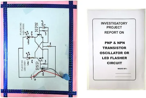
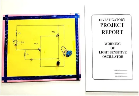
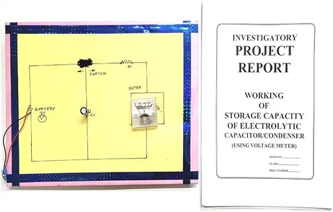
Capacitor Charge Oscillator Physics Working Model Educational Investigatory Project
Code B0C3H5ZP2X
- Paid for and delivered by Amazon. The current price and the delivery date for your PIN code are shown there.
- Sold by Gurukul Technicals Institute, Delhi.
- Need a different topic, a custom version or a school order? Ask on WhatsApp.
In this project guide
Ready-made model
About this model
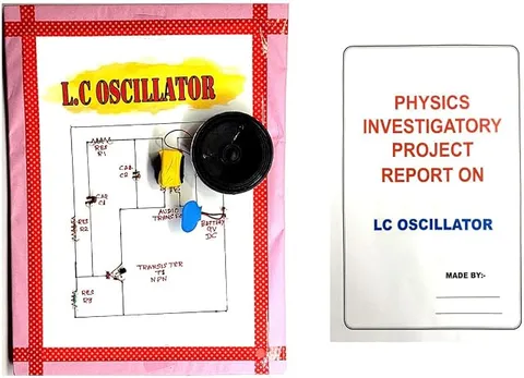
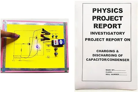
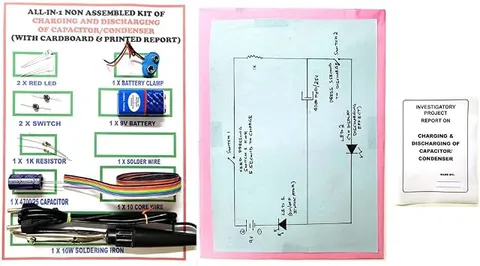
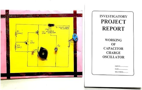
This working model demonstrates a capacitor charge oscillator, a circuit in which a capacitor repeatedly charges and discharges to make a light blink at a steady rate. It shows how a simple component can keep time, which is the basis of electronic timers and clocks. It suits Class 11 and 12 physics investigatory projects.
How it works
The science behind it
The idea the model demonstrates, in words you can use in your report and when you explain it.
A capacitor charging through a resistor does not reach its full voltage instantly; it rises along a curve set by the time constant τ = RC. A relaxation oscillator uses this delay. The capacitor charges until its voltage reaches a switching threshold, at which point a switching element (a transistor, a neon lamp or a timer IC, depending on the circuit) suddenly turns on and lets it discharge, often through the LED, giving a flash. Once the voltage drops below a lower threshold, the switch turns off and charging starts again. The result is a repeating cycle whose period is proportional to RC, so doubling either the resistance or the capacitance roughly doubles the time between flashes. This is different from an LC oscillator, where energy swings back and forth between a capacitor and an inductor. Simple blinking toys and decorative lamps often use this kind of RC timing.
Make it yourself
Make a capacitor charge oscillator yourself
Build your own version from scratch, or use the steps to understand how the ready-made model is put together before you present it.
What you need 9
Step by step 9 steps
Fit the 555 in its socket with the notch or dot marking pin 1, connect pins 4 and 8 to the positive rail and pin 1 to the negative rail.
Connect the 10 kΩ resistor from the positive rail to pin 7, and the 47 kΩ resistor from pin 7 to pin 6.
Join pin 6 to pin 2 with a short wire, so the same capacitor voltage reaches both comparators inside the IC.
Connect the 100 µF capacitor from pin 6 to the negative rail with its marked negative leg to the negative rail, and the 10 nF capacitor from pin 5 to the negative rail.
Connect pin 3 through the 470 Ω resistor to the LED's longer leg, and the LED's shorter leg to the negative rail.
Check every connection, then connect the battery through the switch; the LED should stay on for a few seconds and off for a few seconds, again and again.
Set the multimeter to DC volts across the capacitor and watch the reading climb to about two-thirds of the battery voltage, then fall back to about one-third.
Time ten complete flashes and divide by ten to get the period, then replace the capacitor with 47 µF and 10 µF and repeat.
Compare your periods with T ≈ 0.693 × (R1 + 2R2) × C, where R1 is 10 kΩ and R2 is 47 kΩ, and plot period against capacitance.
Read this first
Safety first
Go through these points before you build or switch anything on. Younger students should do this with an adult.
- Fit electrolytic capacitors the right way round and use ones rated above the battery voltage; a reversed electrolytic can swell or burst.
- Check the IC's orientation before connecting the battery, and disconnect at once if the IC gets warm.
- Do not short the 9 V battery terminals, and unclip it when you finish.
- Solder only with an adult and rest the hot iron in its stand.
Troubleshooting
If something does not work
The usual problems with this model and how to fix them. Open a problem to see the fix.
The LED stays on and never blinks
Check that pins 2 and 6 are joined, that the capacitor really reaches them, and that pin 7 sits between the two resistors. A capacitor leg in the wrong breadboard row is the commonest cause.
The LED never lights
Turn the LED round so its longer leg faces the resistor from pin 3, check that pin 4 is connected to positive, and try a fresh battery.
My measured period does not match the formula
Electrolytic capacitors are often 20% or more away from their marked value, so a difference of that size is normal. Timing ten cycles instead of one also reduces your error.
The multimeter reading jumps instead of climbing smoothly
Use the 100 µF capacitor so each cycle lasts several seconds, and let the meter settle; most meters update only a few times a second.
Exhibition day
How to present it
A running order for the exhibition table or the practical, step by step.
Count the flashes in one minute and calculate the time period of the oscillation.
If the board allows it, change the capacitor or resistor and show the blink rate changing.
Draw a graph of capacitor voltage against time, a rising curve and a sudden drop, and mark when the LED flashes.
Explain why the circuit keeps running on its own without anyone pressing a switch.
Practice
Viva questions
Practice questions on this model, with short answers. Try each one aloud before you open the answer.
What decides the frequency of this oscillator?
Mainly the resistance and capacitance, since the period is proportional to the time constant RC.
What is a relaxation oscillator?
An oscillator in which a capacitor slowly charges and then quickly discharges when a threshold is reached, repeating the cycle.
What happens to the blink rate if the capacitance is doubled?
The time period roughly doubles, so the LED blinks about half as often.
How is this different from an LC oscillator?
An LC oscillator exchanges energy between an inductor and a capacitor to give sine-like oscillations, while this circuit relies on RC charging and switching.
Project file
Project file outline
The headings of the project file, in order. Give each heading its own section and write it in your own words.
Free ebook: Writing a Science Project FileContents
- Aim: to study how charging and discharging a capacitor through resistors produces steady oscillations
- Theory: charging a capacitor through a resistor and the time constant RC
- The 555 timer as a relaxation oscillator: comparators, threshold levels and the discharge pin
- Circuit diagram and list of components with their values
- Construction and testing
- Observation table: capacitance, time for ten flashes and period
- Graph of period against capacitance, with calculated values compared
- Sources of error, precautions and uses in timers, clocks and indicators
- Conclusion
Buying checklist
Before you buy
What to check before you order the model, and what to do when it arrives.
1Before you order
- Confirm with your teacher whether you need only a working circuit or also readings and a graph, and check what the listing says about the circuit used.
- Look in the listing for any mention of a battery or report; do not assume either is included.
- Make sure you can point out the capacitor, the resistors and the IC on the board before the practical.
- Keep it in its box with padding so the components are not bent in transport.
- Check the delivery date for your PIN code on the marketplace, and order well before the exhibition or practical.
2When it arrives
- When it arrives, run it for a few minutes and note the flash rate so you can explain it in the viva.
Next steps
Take it further
Ways to turn this model into a bigger investigation or a stronger exhibition entry.
Build a plain resistor and capacitor circuit with a large capacitor, read its voltage every five seconds as it charges, and find when it reaches about 63% of the battery voltage; compare that time with RC.
Replace the 47 kΩ resistor with a potentiometer and show how the flash rate changes as you turn it.
Use a 10 nF timing capacitor and a small speaker connected through a 10 µF capacitor and a 100 Ω resistor to hear the oscillation as a tone, and explain why a smaller capacitor gives a higher pitch.
Audience
Who it suits
Class 11 and 12 physics investigatory projects on capacitors and oscillations, and electronics hobby clubs.
- ClassClass 10 to 12
- SubjectPhysics
- TypeReady-made model
Free to read
Free ebooks for this topic
Free PDF ebooks from Gurukul Technicals Institute on the science, the making and the presenting of projects like this one.
- Free PDF ebook
Physics Working Models Explained
Twenty classic models, how each works and how to make it
- Free PDF ebook
Investigatory Projects for Class 11 and 12
Topics, method and report structure for physics, chemistry and biology
- Free PDF ebook
Your Science Exhibition Guide
Choose a project, build it, present it and answer the judges with confidence
- Free PDF ebook
Writing a Science Project File
How to write the report, from the cover page to the bibliography