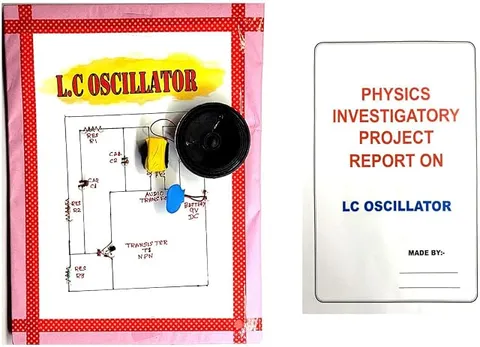
- Physics
- Ready-made model
- Class 10 to 12
- Printed report included
LC Oscillator Physics Investigatory Working Project Model with Report
Code B0G2T7HMR2
- Paid for and delivered by Amazon. The current price and the delivery date for your PIN code are shown there.
- Sold by Gurukul Technicals Institute, Delhi.
- Need a different topic, a custom version or a school order? Ask on WhatsApp.
In this project guide
Ready-made model
About this model
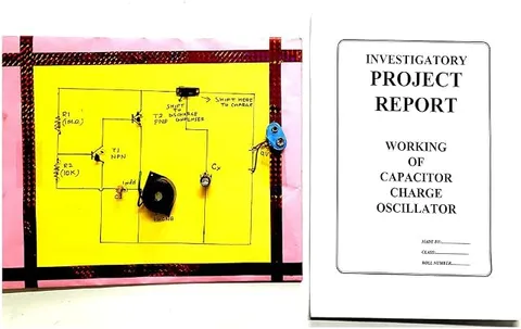
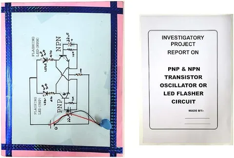
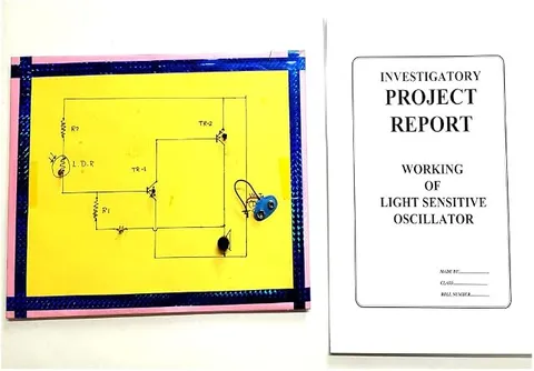
This physics investigatory model is about the LC oscillator, a circuit in which an inductor and a capacitor pass energy back and forth to produce electrical oscillations. The listing says a report is included, which is useful when writing up the project file.
How it works
The science behind it
The idea the model demonstrates, in words you can use in your report and when you explain it.
When a charged capacitor C is connected across an inductor L, it starts to discharge and current flows through the coil, building up a magnetic field. When the capacitor is empty, the energy is stored in the inductor's magnetic field, ½LI². The current keeps flowing, because an inductor opposes any change in current, and charges the capacitor with the opposite polarity, storing the energy in its electric field, ½CV². The process repeats, so charge and current oscillate at a natural frequency f = 1 ÷ (2π√(LC)); for L = 1 mH and C = 1 µF, f is about 5 kHz. In a real circuit, resistance turns some energy into heat in every cycle, so the oscillations die out. An oscillator circuit adds an amplifier, usually a transistor, with positive feedback to replace this lost energy and keep the oscillations going. In an analogue radio, turning the tuning knob changes C to match the frequency of the station you want.
Make it yourself
Make an LC oscillator model yourself
Build your own version from scratch, or use the steps to understand how the ready-made model is put together before you present it.
What you need 9
Step by step 8 steps
Wire the two-way switch so that in position A the capacitor charges from the 1.5 V cell through the 100 ohm resistor, and in position B it connects across the coil and the galvanometer in series.
Hold the switch in position A for a few seconds to charge the capacitor.
Flip the switch to B and watch the galvanometer needle swing one way and then the other, each swing smaller than the last; with most coils you will see only a few swings.
Count the swings and time several of them with the stopwatch to find the time period.
Change the capacitance by adding a second capacitor in parallel, and measure the period again.
Lift the iron yoke slightly, or pull the core partly out of the coil, to lower its inductance, and see the swings speed up.
For continuous oscillations, build a transistor Colpitts oscillator on the breadboard from a tested circuit diagram, with the piezo earpiece at its output.
Swap the capacitors in its tank circuit and listen to the pitch rise as the capacitance falls.
Read this first
Safety first
Go through these points before you build or switch anything on. Younger students should do this with an adult.
- Use only the 1.5 V cell and the 9 V battery. Never connect a large coil straight to a battery and then break the circuit, because its collapsing magnetic field can give a sharp high-voltage kick.
- Connect electrolytic capacitors the right way round, discharge them before handling, and keep your face away while testing; a reversed electrolytic can bulge or burst.
- Flip the switch back to the charging side only after the needle has stopped swinging.
- Solder only with an adult present.
Troubleshooting
If something does not work
The usual problems with this model and how to fix them. Open a problem to see the fix.
The needle moves once and stops, without swinging back
The oscillation is too heavily damped: the coil's resistance is large compared with √(L ÷ C). Try a smaller capacitor, close the iron core fully and keep the wires short, or ask your teacher to show the decaying oscillation on the school oscilloscope.
The needle hits the end of the scale
The current is too large for the galvanometer. Fit a shunt wire across it as your teacher shows, or charge the capacitor to a lower voltage.
The Colpitts oscillator makes no sound
Check the transistor's pins, its bias resistors and the feedback link from the capacitor junction. With a very small coil the pitch may be too high to hear.
My measured frequency does not match the formula
Real capacitors can differ a lot from their marked values, and a homemade coil's inductance is unknown. Ask your teacher to measure L and C with an LCR meter.
Exhibition day
How to present it
A running order for the exhibition table or the practical, step by step.
Explain the energy swing between capacitor and inductor using a swinging pendulum as an analogy.
Write f = 1 ÷ (2π√(LC)) on a chart with one worked example, and show what happens to f when C or L is increased.
If your school lab has a CRO, display the waveform to show the oscillations.
Explain why a transistor and feedback are needed for oscillations that do not die out.
Practice
Viva questions
Practice questions on this model, with short answers. Try each one aloud before you open the answer.
What is the formula for the frequency of an LC circuit?
f = 1 ÷ (2π√(LC)), where L is the inductance in henry and C is the capacitance in farad.
What energy changes take place in an LC circuit?
Energy keeps changing from the electric field of the capacitor to the magnetic field of the inductor and back again.
Why do the oscillations in a real LC circuit die out?
The resistance of the wires and coil converts some energy into heat in every cycle, so the amplitude keeps decreasing.
If the capacitance is made four times larger, what happens to the frequency?
The frequency becomes half, because f is inversely proportional to the square root of C.
Project file
Project file outline
The headings of the project file, in order. Give each heading its own section and write it in your own words.
The listing includes a printed project report: use this outline to check that your own file covers every part.
Free ebook: Writing a Science Project FileContents
- Aim: to study electrical oscillations in an LC circuit and how their frequency depends on L and C
- Apparatus
- Theory: exchange of energy between the capacitor and the inductor
- Circuit diagrams of the damped and the sustained oscillator
- Procedure
- Observation table: capacitance, number of swings and time period
- Comparison of measured and calculated frequencies
- Damping and the role of resistance
- Result and precautions
Buying checklist
Before you buy
What to check before you order the model, and what to do when it arrives.
1Before you order
- LC oscillations are a senior secondary physics topic; check that it matches what your teacher has set.
- Check in the listing what the model needs to run, such as a battery, and how it shows the oscillation, for example a meter or a speaker.
- Test the model a few days before submission and keep a fresh battery.
- Keep the box so the coil and capacitors are not knocked loose.
- Check the delivery date for your PIN code on the marketplace, and order well before the exhibition or practical.
- The project report is a learning aid. Read it, understand how the model works, and write your own observations; schools expect your own work.
- Practise explaining it. Judges ask what the model shows and why; knowing the science matters as much as the model. The viva questions above are a good place to start.
2When it arrives
- If a report is included, check that its circuit diagram matches the model you receive before copying it into your file.
Next steps
Take it further
Ways to turn this model into a bigger investigation or a stronger exhibition entry.
Plot T² against C: a straight line confirms that the period depends on the square root of C, and its slope divided by 4π² gives L.
Add resistors in series with the coil and show how the damping increases.
Use the tank circuit to tune a simple crystal radio and explain resonance.
Audience
Who it suits
Suits Class 12 physics investigatory projects on alternating current and electronics, and diploma students studying oscillators.
- ClassClass 10 to 12
- SubjectPhysics
- TypeReady-made model
- Project reportPrinted report included
Free to read
Free ebooks for this topic
Free PDF ebooks from Gurukul Technicals Institute on the science, the making and the presenting of projects like this one.
- Free PDF ebook
Physics Working Models Explained
Twenty classic models, how each works and how to make it
- Free PDF ebook
Investigatory Projects for Class 11 and 12
Topics, method and report structure for physics, chemistry and biology
- Free PDF ebook
Your Science Exhibition Guide
Choose a project, build it, present it and answer the judges with confidence
- Free PDF ebook
Writing a Science Project File
How to write the report, from the cover page to the bibliography