- Physics
- Ready-made model
- Class 10 to 12
- Printed report included
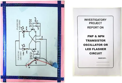
Flasher Circuit NPN PNP Oscillator with Report Physics Educational Investigatory Project for School & Colleges
Code B0DK25WBDW
- Paid for and delivered by Amazon. The current price and the delivery date for your PIN code are shown there.
- Sold by Gurukul Technicals Institute, Delhi.
- Need a different topic, a custom version or a school order? Ask on WhatsApp.
In this project guide
Ready-made model
About this model
This investigatory project is a flasher circuit that uses an NPN and a PNP transistor together as an oscillator to blink a light, and the listing says it includes a report. It is a compact way to learn how the two types of transistor differ. It also shows how positive feedback produces oscillations, a topic that impresses examiners when explained well.
How it works
The science behind it
The idea the model demonstrates, in words you can use in your report and when you explain it.
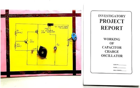
NPN and PNP transistors are mirror images. An NPN transistor turns on when its base is made about 0.7 V more positive than its emitter, while a PNP transistor turns on when its base is about 0.7 V more negative than its emitter. In a complementary flasher, the collector of the NPN transistor drives the base of the PNP transistor, and the PNP's output, which also lights the LED or lamp, is fed back to the NPN's base through a capacitor. This is positive feedback: once the NPN starts conducting, the PNP turns on, and the capacitor pushes the NPN harder on, so both snap fully on and the light flashes. As the capacitor charges, the base drive fades, both transistors switch off, and the capacitor discharges through the resistors until the cycle repeats. The flash rate depends on the RC values. The blinking lamps on barricades at road works use a similar idea.
Make it yourself
Make an NPN-PNP transistor flasher yourself
Build your own version from scratch, or use the steps to understand how the ready-made model is put together before you present it.
What you need 8
Step by step 8 steps
Find the emitter, base and collector of both transistors from their datasheets and mark them on a sketch, remembering that a PNP is connected the opposite way round to an NPN.
Connect the NPN emitter to the negative rail and the PNP emitter to the positive rail, and fit one 1 kΩ resistor between the PNP's base and emitter.
Connect the NPN collector through the second 1 kΩ resistor to the PNP base, so that when the NPN conducts it pulls the PNP base down and switches the PNP on.
From the PNP collector, connect the 330 Ω resistor and the LED in series to the negative rail (longer LED leg towards the resistor), and the third 1 kΩ resistor straight to the negative rail.
Connect the 100 kΩ resistor and the preset in series from the positive rail to the NPN base, with the preset turned to its highest resistance.
Connect the 10 µF capacitor from the PNP collector to the NPN base, positive leg towards the PNP collector; this is the positive feedback path.
Switch on and adjust the preset slowly: if the LED stays lit, turn it towards higher resistance; if it stays dark, turn it back. It flashes in a band between the two, so leave it in the middle of that band.
Time twenty flashes at a few preset positions, then swap the capacitor for 4.7 µF and 22 µF, re-tune and repeat.
Read this first
Safety first
Go through these points before you build or switch anything on. Younger students should do this with an adult.
- Use only the 4.5 V cell pack: in this circuit the NPN base is pulled below zero volts on every cycle, and a much higher supply can push it past its safe reverse voltage.
- Fit the electrolytic capacitor the right way round, and check each transistor's pins before switching on; a wrongly connected transistor can overheat within seconds.
- Switch off before moving any component on the breadboard.
- Solder only with an adult and keep the hot iron in its stand.
Troubleshooting
If something does not work
The usual problems with this model and how to fix them. Open a problem to see the fix.
The LED stays lit all the time
The NPN base is getting too much current, so both transistors stay fully on. Turn the preset towards higher resistance or use a bigger fixed resistor, and check that the capacitor joins the PNP collector to the NPN base.
The LED never lights
Check the pin order of both transistors and the direction of the LED first. If the wiring is right, the base is getting too little current, so turn the preset towards lower resistance.
The flashes are very short and faint
Each flash ends once the capacitor has charged. Put a resistor of a few kilo-ohms in series with the capacitor so each flash lasts longer, then re-tune the preset.
It flashed yesterday but not today
This circuit flashes only within a narrow band of the preset, and the band shifts a little as the cells run down. Fit fresh cells and re-tune it before the exhibition.
Exhibition day
How to present it
A running order for the exhibition table or the practical, step by step.
Identify the NPN and PNP transistors on the board and explain the arrow direction in each symbol.
Count the flashes per minute and relate the rate to the capacitor and resistor values.
Explain positive feedback with a simple block diagram.
Be ready to compare this circuit with a two-NPN astable multivibrator if the examiner asks for alternatives.
Practice
Viva questions
Practice questions on this model, with short answers. Try each one aloud before you open the answer.
What is the difference between NPN and PNP transistors?
In an NPN transistor the current is carried mainly by electrons and the base must be positive relative to the emitter to conduct; in a PNP transistor it is carried mainly by holes and the base must be negative relative to the emitter.
What is the role of the capacitor in the flasher?
It provides positive feedback and, as it charges and discharges through the resistors, sets the timing of the flashes.
What is positive feedback?
Feeding part of the output back to the input in phase so that it reinforces the input; it is needed to sustain oscillations.
How can the flashing rate be changed?
By changing the value of the timing capacitor or resistor; larger values give slower flashing.
Project file
Project file outline
The headings of the project file, in order. Give each heading its own section and write it in your own words.
The listing includes a printed project report: use this outline to check that your own file covers every part.
Free ebook: Writing a Science Project FileContents
- Aim: to make a flasher using an NPN and a PNP transistor together as an oscillator
- NPN and PNP transistors compared: structure, symbols and biasing
- How the NPN switches the PNP on, with the circuit diagram
- Positive feedback through the capacitor and how it makes the circuit snap on and off
- Construction, and how the preset was adjusted to start the flashing
- Observation table: capacitor value, time for twenty flashes and flash rate
- Precautions and sources of error
- Uses of flashers: indicators, warning lights and toys
- Conclusion
Buying checklist
Before you buy
What to check before you order the model.
1Check these first
- Check with your teacher that a transistor flasher suits your class and the chapter on semiconductor devices.
- The listing says a report is included; read it alongside your textbook and add your own readings.
- If the board has a small preset, mark its position with a pen before touching it, so you can return it if the flashing stops.
- Look in the listing for the battery it needs; do not assume one is supplied, and test the board a few days before the exhibition.
- Keep the box and padding so the components are not bent in transit.
- Check the delivery date for your PIN code on the marketplace, and order well before the exhibition or practical.
- Practise explaining it. Judges ask what the model shows and why; knowing the science matters as much as the model. The viva questions above are a good place to start.
Next steps
Take it further
Ways to turn this model into a bigger investigation or a stronger exhibition entry.
Measure the flash rate for several capacitor values and plot it against capacitance.
Build the classic two-NPN astable multivibrator with two LEDs and compare it with this one-capacitor circuit.
Replace the LED and its resistor with a small speaker in series with a 100 Ω resistor and use a much smaller capacitor, so the same circuit produces a tone.
Audience
Who it suits
Class 11 and 12 physics investigatory projects on semiconductor devices, and diploma or engineering electronics labs.
- ClassClass 10 to 12
- SubjectPhysics
- TypeReady-made model
- Project reportPrinted report included
Free to read
Free ebooks for this topic
Free PDF ebooks from Gurukul Technicals Institute on the science, the making and the presenting of projects like this one.
- Free PDF ebook
Electricity and Magnetism Experiments
Hands-on experiments with cells, wires, bulbs and magnets
- Free PDF ebook
Physics Working Models Explained
Twenty classic models, how each works and how to make it
- Free PDF ebook
Investigatory Projects for Class 11 and 12
Topics, method and report structure for physics, chemistry and biology
- Free PDF ebook
Your Science Exhibition Guide
Choose a project, build it, present it and answer the judges with confidence