- Physics
- Ready-made model
- Class 10 to 12
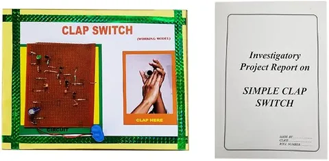
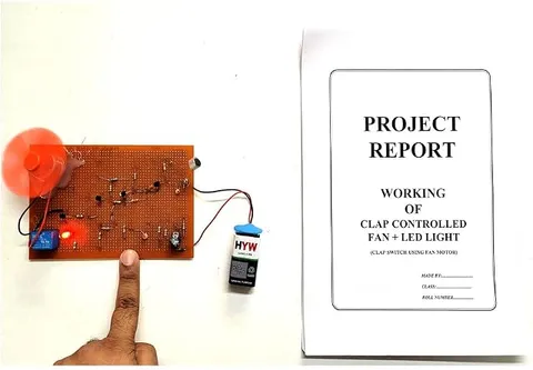
Clap Controlled LED Light and Fan Handmade Investigatory Minor Project on Multipurpose PCB
Code B0C3H77JG2
- Paid for and delivered by Amazon. The current price and the delivery date for your PIN code are shown there.
- Sold by Gurukul Technicals Institute, Delhi.
- Need a different topic, a custom version or a school order? Ask on WhatsApp.
In this project guide
Ready-made model
About this model
This handmade minor project switches an LED light and a fan on and off with a clap, built on a multipurpose PCB according to its title. It shows how a sound can be turned into an electrical signal and used to control devices, the same idea behind many sound-activated gadgets. It is a lively exhibition piece and a good Class 9 to 12 minor project.
How it works
The science behind it
The idea the model demonstrates, in words you can use in your report and when you explain it.
The circuit works as a chain of stages. Usually a small condenser (electret) microphone first converts the sound of the clap into a tiny electrical signal: the sound wave makes a thin diaphragm vibrate, changing the capacitance between it and a back plate. This signal is far too weak to drive anything, so one or more transistors amplify it. The amplified pulse then triggers a toggle stage, a flip-flop built from transistors or an IC, which remembers its state: the first clap sets it ON and the next sets it OFF. Finally, a transistor or relay switches the loads: the LED for light and a small motor for the fan. A clap makes a good trigger because it is short and sharp, with a sudden rise in loudness that the circuit can tell apart from steady background noise. The same chain of sense, amplify, decide and act is found in automatic gadgets from smoke alarms to smart speakers.
Make it yourself
Make a clap-controlled light and fan yourself
Build your own version from scratch, or use the steps to understand how the ready-made model is put together before you present it.
What you need 10
Step by step 8 steps
Draw the block diagram first, microphone, amplifier, pulse stage, counter and drivers, so you know what each part of the board does.
- Build the microphone stage
Power the microphone through its 10 kΩ resistor and couple it through a 100 nF capacitor to the amplifier, with the potentiometer setting its gain.
Feed the amplifier output to pin 2 of the 555 wired as a monostable, so each clap gives one pulse of about half a second and the clap's echoes are ignored.
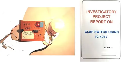
Connect the 555 output to the clock input of the CD4017, tie its enable pin to the negative rail, and join output Q3 to its reset pin, so it counts Q0 (off), Q1 (light), Q2 (fan) and then starts again.
Connect Q1 through a resistor to the base of one driver transistor that switches the LEDs, and Q2 to the second driver that switches the motor.
Fit the 1N4007 across the motor with its band towards the positive side, to absorb the voltage spike the motor makes when it switches off.
Check the polarity of the microphone (its negative pad is joined to its metal case), the electrolytic capacitors and both ICs, then power the board from the 6 V pack.
Clap once for the light, again for the fan and a third time for off, and turn the potentiometer until normal talking does not trigger it.
Read this first
Safety first
Go through these points before you build or switch anything on. Younger students should do this with an adult.
- Use a soft, light plastic fan blade and keep fingers away while it spins.
- Run the project only on the 6 V cell pack; never connect it to an adapter or the mains.
- Always fit the diode across the motor, because without it the switching spike can destroy the driver transistor.
- Solder only with an adult, and touch a grounded metal object before handling the CMOS counter IC so static does not damage it.
Troubleshooting
If something does not work
The usual problems with this model and how to fix them. Open a problem to see the fix.
It switches on random noises
The amplifier is too sensitive. Turn the potentiometer down, and keep the microphone away from the fan, whose own noise can trigger it.
One clap jumps two steps
The clap's echo is being counted as a second clap. Lengthen the 555 pulse with a larger timing capacitor so it ignores sound for longer after each clap.
The LEDs work but the fan does not start
The motor needs more current than it is getting, or the cells are weak. Fit fresh cells, check the driver transistor's pins, and give the blade a gentle push to see if the motor is just stiff.
Nothing responds to claps at all
Check that the microphone is the right way round and that both ICs have power on their supply pins. Test the amplifier alone with an LED to see whether it reacts to a clap.
Exhibition day
How to present it
A running order for the exhibition table or the practical, step by step.
Show one clap turning both devices on and the next clap turning them off, and explain the memory that makes this possible.
Draw a block diagram: microphone, amplifier, flip-flop, driver, load.
Show that a sharp clap triggers it more reliably than ordinary talking, and explain why.
Keep the microphone facing the audience and away from the breeze of the fan.
Practice
Viva questions
Practice questions on this model, with short answers. Try each one aloud before you open the answer.
What is the role of the microphone in this project?
It converts the sound energy of the clap into a small electrical signal.
Why is an amplifier needed?
The microphone signal is very weak, so transistors amplify it enough to trigger the switching stage.
How does the circuit remember whether the load is on or off?
A flip-flop (bistable) stage changes state with each pulse and holds that state until the next clap.
What energy changes take place in this project?
Sound energy becomes electrical energy, which is then converted into light by the LED and into motion by the fan motor.
Project file
Project file outline
The headings of the project file, in order. Give each heading its own section and write it in your own words.
Free ebook: Writing a Science Project FileContents
- Aim: to control an LED light and a fan with claps
- How an electret microphone turns sound into an electrical signal
- Block diagram: amplifier, pulse stage, counter and drivers
- Why each clap must give one clean pulse: echoes and the 555 monostable
- How the CD4017 counter steps between off, light and fan
- Driving a motor safely: the transistor driver and the protection diode
- Construction on the multipurpose PCB, with photographs
- Observations: distance and loudness at which claps are detected
- Uses for elderly and disabled people, and conclusion
Buying checklist
Before you buy
What to check before you order the model, and what to do when it arrives.
1Before you order
- The title calls it a minor project; check with your teacher that it suits your class and syllabus.
- Read the listing for the battery or supply it needs; do not assume one is included.
- Check that the fan blade is fixed firmly and spins freely.
- Keep the box so the fan and the PCB travel safely.
- Check the delivery date for your PIN code on the marketplace, and order well before the exhibition or practical.
- Practise explaining it. Judges ask what the model shows and why; knowing the science matters as much as the model. The viva questions above are a good place to start.
2When it arrives
- When it arrives, test it in a quiet room and in a noisy one a few days before the exhibition, because an exhibition hall is loud.
Next steps
Take it further
Ways to turn this model into a bigger investigation or a stronger exhibition entry.
Replace the fan step with a relay so the second clap switches a separate low-voltage lamp circuit, keeping the two circuits isolated.
Measure how far away a clap still works at different sensitivity settings and present it as a graph.
Rebuild the control part with a sound sensor module and a microcontroller board that responds only to a double clap.
Audience
Who it suits
Class 9 to 12 minor projects and science exhibitions on sound-controlled electronics.
- ClassClass 10 to 12
- SubjectPhysics
- TypeReady-made model
Free to read
Free ebooks for this topic
Free PDF ebooks from Gurukul Technicals Institute on the science, the making and the presenting of projects like this one.
- Free PDF ebook
Electricity and Magnetism Experiments
Hands-on experiments with cells, wires, bulbs and magnets
- Free PDF ebook
Physics Working Models Explained
Twenty classic models, how each works and how to make it
- Free PDF ebook
Investigatory Projects for Class 11 and 12
Topics, method and report structure for physics, chemistry and biology
- Free PDF ebook
Your Science Exhibition Guide
Choose a project, build it, present it and answer the judges with confidence