- Physics
- Ready-made model
- Class 10 to 12
LED Chaser Sequence Light Physics Working Model Educational Investigatory Project
Code B0BN2FR3TX
- Paid for and delivered by Amazon. The current price and the delivery date for your PIN code are shown there.
- Sold by Gurukul Technicals Institute, Delhi.
- Need a different topic, a custom version or a school order? Ask on WhatsApp.
In this project guide
Ready-made model
About this model
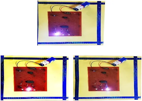
This LED chaser lights a row of LEDs one after another, so the light seems to run along the line. It is an eye-catching working model that demonstrates clock pulses, counting and sequencing in digital electronics.
How it works
The science behind it
The idea the model demonstrates, in words you can use in your report and when you explain it.
A typical LED chaser has two main parts. A 555 timer in astable mode acts as a clock, producing a steady stream of square pulses whose rate is set by resistors and a capacitor, often with a variable resistor to change the speed. These pulses go to a decade counter IC such as the CD4017, which has ten outputs. With each pulse, the counter moves its single HIGH output from one pin to the next, 0, 1, 2 and so on up to 9, and then starts again. An LED on each output lights only while its pin is HIGH, so the light appears to move along the row. When the pulses are fast, persistence of vision blends the moving dot into a smooth running streak. Each LED usually has a series resistor to limit its current so it does not burn out. The decorative lights put up for Diwali and weddings create their chasing patterns on this same principle.
Make it yourself
Make a ten-LED chaser with speed control yourself
Build your own version from scratch, or use the steps to understand how the ready-made model is put together before you present it.
What you need 9
Step by step 8 steps
Build the 555 as a clock: 1 kΩ from pin 8 to pin 7, the 4.7 kΩ and the potentiometer (one outer pin and the middle pin) in series from pin 7 to pins 2 and 6 (joined), 10 µF from pins 2 and 6 to negative, pins 4 and 8 to positive, pin 1 to negative, and 0.01 µF from pin 5 to negative.
- Wire the CD4017
Pin 16 to positive, pins 8, 13 and 15 to negative, and pin 14 to the 555's pin 3.
Connect each LED's long leg to one output in order: Q0 pin 3, Q1 pin 2, Q2 pin 4, Q3 pin 7, Q4 pin 10, Q5 pin 1, Q6 pin 5, Q7 pin 6, Q8 pin 9 and Q9 pin 11.
Join all ten short legs together and connect them to negative through the single 470 Ω resistor; one resistor is enough because only one LED is lit at a time.
Fit the ICs with their notches the right way, switch on, and turn the potentiometer to make the light run slowly and then quickly.
Mount the LEDs on the foam board in your chosen pattern, keeping them in output order so the light runs smoothly.
Time five complete runs of ten LEDs at three potentiometer settings, and work out the clock frequency in steps per second.
Swap the 10 µF capacitor for the 0.1 µF one: the clock runs about a hundred times faster and the row looks steadily lit, because of persistence of vision.
Read this first
Safety first
Go through these points before you build or switch anything on. Younger students should do this with an adult.
- Use the soldering iron only with an adult, rest it in its stand, and let joints cool before touching.
- Never leave out the 470 Ω resistor in the shared line; without it the LEDs and the counter can be damaged.
- Fit the ICs and the 10 µF capacitor the right way round, and switch off before changing parts.
- If anyone watching is sensitive to flashing lights, keep the speed slow and avoid fast flicker.
Troubleshooting
If something does not work
The usual problems with this model and how to fix them. Open a problem to see the fix.
One LED stays lit and nothing moves
The clock is not running, or pin 13 is not at negative. Check the 555's wiring and capacitor, and connect pin 13 to negative.
The LEDs light out of order
The 4017's outputs are not in pin order. Check each LED against the output list.
The run stops after a few LEDs and starts again
The reset, pin 15, is touching an output or is loose. Connect it firmly to negative.
Turning the speed knob does nothing
The potentiometer is connected by its two outer pins, which is a fixed resistance. Use one outer pin and the middle pin.
Exhibition day
How to present it
A running order for the exhibition table or the practical, step by step.
If the model has a speed control, change it and explain which part of the circuit sets the speed.
Explain how the counter moves its output one step on each clock pulse.
Draw a simple block diagram: clock, counter and LEDs.
Link it to Diwali decoration lights to make the idea familiar.
Practice
Viva questions
Practice questions on this model, with short answers. Try each one aloud before you open the answer.
In a typical LED chaser, what is the role of the 555 timer?
It works as an astable oscillator that produces the clock pulses which step the counter.
What does a decade counter do?
It counts input pulses from 0 to 9, moving its HIGH output one step on each pulse, and then starts again.
How can the chasing speed be changed?
By changing the resistance or capacitance in the 555 timing circuit, which changes the clock frequency.
Why is a resistor used with each LED?
To limit the current through the LED so that it does not burn out.
Project file
Project file outline
The headings of the project file, in order. Give each heading its own section and write it in your own words.
Free ebook: Writing a Science Project FileContents
- Aim: to make a row of LEDs light one after another at a speed that can be controlled
- Introduction: running lights in signs, decorations and vehicle indicators
- The 555 timer as a clock and f ≈ 1.44 / ((R1 + 2R2) × C)
- The CD4017 decade counter and its ten outputs
- Circuit diagram and construction
- Observations: measured steps per second against calculated frequency
- Persistence of vision at high speed
- Applications: running signboards, sequential indicators and display effects
- Conclusion and bibliography
Buying checklist
Before you buy
What to check before you order the model, and what to do when it arrives.
1Before you order
- Check that clock pulses and counters fit your syllabus and your teacher's brief.
- Read the listing to see whether the speed can be changed and what powers the model.
- Practise explaining what the 555 and the 4017 each do, as these are the usual viva questions.
- Keep the box so the LEDs are not bent in transport.
- Check the delivery date for your PIN code on the marketplace, and order well before the exhibition or practical.
2When it arrives
- Run it at different speeds as soon as it arrives, and again a few days before the exhibition.
Next steps
Take it further
Ways to turn this model into a bigger investigation or a stronger exhibition entry.
Use diodes to make the light run forwards and back across six LEDs, like a scanner.
Cascade two CD4017 counters to run twenty LEDs.
Plot frequency against 1/C for three capacitors and compare the slope with the 555 formula.
Audience
Who it suits
Class 9 to 12 students and electronics beginners looking for an eye-catching digital electronics project.
- ClassClass 10 to 12
- SubjectPhysics
- TypeReady-made model
Free to read
Free ebooks for this topic
Free PDF ebooks from Gurukul Technicals Institute on the science, the making and the presenting of projects like this one.
- Free PDF ebook
Electricity and Magnetism Experiments
Hands-on experiments with cells, wires, bulbs and magnets
- Free PDF ebook
Physics Working Models Explained
Twenty classic models, how each works and how to make it
- Free PDF ebook
Investigatory Projects for Class 11 and 12
Topics, method and report structure for physics, chemistry and biology
- Free PDF ebook
Your Science Exhibition Guide
Choose a project, build it, present it and answer the judges with confidence