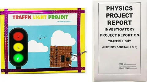
- Physics
- Ready-made model
- Class 10 to 12
- Printed report included
Traffic Light Readymade Physics Working Project & Model for School & Colleges(with Printed Report)
Code B099QZ7JQX
- Paid for and delivered by Amazon. The current price and the delivery date for your PIN code are shown there.
- Sold by Gurukul Technicals Institute, Delhi.
- Need a different topic, a custom version or a school order? Ask on WhatsApp.
In this project guide
Ready-made model
About this model
This readymade traffic light model runs through the red, yellow and green signal sequence used at road crossings. It shows how an electronic circuit switches lights in a fixed order and for set times, and the listing says a printed report is included.
How it works
The science behind it
The idea the model demonstrates, in words you can use in your report and when you explain it.
A traffic light is a sequencing circuit: it switches its lamps on one after another in a fixed order and for set times. In many school models, a timer IC such as the 555 produces regular clock pulses and a counter IC moves its output from one step to the next with each pulse. Several steps can be wired to the red and green lamps and fewer to yellow, so red and green stay on longer. Red is used for stop because it has the longest wavelength of visible light and is scattered least by air, dust and fog, so it can be seen clearly from far away. Green is easy to tell apart from red, and yellow warns drivers that the signal is about to change. Traffic signals at busy junctions in our cities follow this kind of timed sequence, and many now also show a countdown timer so that drivers know how long the light will last.
Make it yourself
Make a timed traffic light model yourself
Build your own version from scratch, or use the steps to understand how the ready-made model is put together before you present it.
What you need 9
Step by step 8 steps
Build the 555 as a clock: pin 1 to negative, pins 4 and 8 to positive, the 10 kΩ from pin 8 to pin 7, the 47 kΩ and the preset in series from pin 7 to pins 2 and 6 (joined), the 47 µF from pins 2 and 6 to negative, and the 0.01 µF from pin 5 to negative.
- Wire the CD4017
Pin 16 to positive, pins 8, 13 and 15 to negative, and the clock input, pin 14, to the 555's output, pin 3.
Use the diodes to give each colour several counts, with each diode's band towards the LED: outputs Q0 to Q3 (pins 3, 2, 4 and 7) to the red LED's resistor, Q4 to Q7 (pins 10, 1, 5 and 6) to the green, and Q8 and Q9 (pins 9 and 11) to the yellow.
Connect each LED's long leg to its resistor and its short leg to negative.
Fit both ICs with their notches the right way, switch on, and check the order: red, then green, then yellow, then red again.
Time each colour with the stopwatch and set the preset so that each count lasts about 4 seconds, which gives about 16 seconds of red, 16 of green and 8 of yellow.
Mount the LEDs in the black post with red at the top, yellow in the middle and green at the bottom, and stand it at the corner of the road junction with a zebra crossing and stop line.
Label the 555 as the clock and the 4017 as the counter on the board so visitors can follow the signal.
Read this first
Safety first
Go through these points before you build or switch anything on. Younger students should do this with an adult.
- Use the soldering iron only with an adult, rest it in its stand, and let joints cool before touching them.
- Fit the ICs and the 47 µF capacitor the right way round; a reversed IC can overheat and a reversed capacitor can burst.
- Run the model only from the 9 V battery and switch it off between demonstrations.
- Trim component legs with the cutters pointing down, away from your eyes.
Troubleshooting
If something does not work
The usual problems with this model and how to fix them. Open a problem to see the fix.
Two colours light at the same time
A diode is in backwards or missing, so one output feeds another colour. Check that every band faces the LED side and that each output has exactly one diode.
The lights change far too fast, or not at all
The timing capacitor may be the wrong value, for example 0.47 µF instead of 47 µF, or the 555 is wired wrongly. Connect an LED and resistor straight to pin 3: it should blink once every few seconds.
The sequence sticks on one colour
Pin 13 or pin 15 of the 4017 has been left unconnected; both must go to negative. Also check that pin 3 of the 555 reaches pin 14.
Yellow comes before green
The outputs are on the wrong colours. The 4017's outputs are not in pin order, so check each one against the pin list.
Exhibition day
How to present it
A running order for the exhibition table or the practical, step by step.
Run the full sequence and explain what drivers and walkers should do at each colour.
Explain why red is chosen for stop, using the idea of scattering of light.
Draw a simple block diagram: clock, counter and lights.
Add a short road safety message to your chart.
Practice
Viva questions
Practice questions on this model, with short answers. Try each one aloud before you open the answer.
Why is red used for the stop signal?
Red light has the longest wavelength in the visible spectrum and is scattered least, so it can be seen from a long distance even in fog.
What does the yellow light mean?
It warns that the signal is about to change, so drivers should get ready to stop.
What is a sequencing circuit?
A circuit that switches its outputs on one after another in a fixed order, often using a clock and a counter.
What is the role of clock pulses in such a circuit?
Each pulse moves the counter to its next step, so the pulses set the timing of the sequence.
Project file
Project file outline
The headings of the project file, in order. Give each heading its own section and write it in your own words.
The listing includes a printed project report: use this outline to check that your own file covers every part.
Free ebook: Writing a Science Project FileContents
- Aim: to make a traffic light that changes colour in a fixed order and for set times
- Introduction: why road junctions need signals
- Why red means stop: wavelength and scattering of light
- The 555 timer as a clock, with f ≈ 1.44 / ((R1 + 2R2) × C)
- The CD4017 counter and the diode connections for each colour
- Circuit diagram and component list
- Observations: measured time for each colour against the calculated time
- Real traffic signals: timers, sensors and pedestrian crossings
- Precautions and conclusion
Buying checklist
Before you buy
What to check before you order the model, and what to do when it arrives.
1Before you order
- Check that the project suits your class: a timer-and-counter circuit fits senior physics, while younger classes may mainly need to explain road safety.
- Read the listing to see what powers the model, and keep a fresh battery ready.
- Keep the box so the signal post is not bent in transport.
- Check the delivery date for your PIN code on the marketplace, and order well before the exhibition or practical.
2When it arrives
- The listing says a printed report is included; check it when the parcel arrives and add your own timing readings.
- Run it through several full cycles as soon as it arrives and again a few days before the exhibition.
Next steps
Take it further
Ways to turn this model into a bigger investigation or a stronger exhibition entry.
Add a second set of lights for the crossing road, wired so it shows red whenever the first set shows green.
Add a pedestrian push button that lights a 'walk' LED during the red phase.
Calculate the step time from the 555 formula and compare it with the stopwatch readings, explaining the difference with component tolerances.
Audience
Who it suits
Class 5 to 10 students preparing an exhibition model on road safety, light or simple electronics.
- ClassClass 10 to 12
- SubjectPhysics
- TypeReady-made model
- Project reportPrinted report included
Free to read
Free ebooks for this topic
Free PDF ebooks from Gurukul Technicals Institute on the science, the making and the presenting of projects like this one.
- Free PDF ebook
Physics Working Models Explained
Twenty classic models, how each works and how to make it
- Free PDF ebook
Your Science Exhibition Guide
Choose a project, build it, present it and answer the judges with confidence
- Free PDF ebook
Writing a Science Project File
How to write the report, from the cover page to the bibliography
- Free PDF ebook
Viva Questions for Science Projects
How to answer examiner questions, with sample questions for popular projects