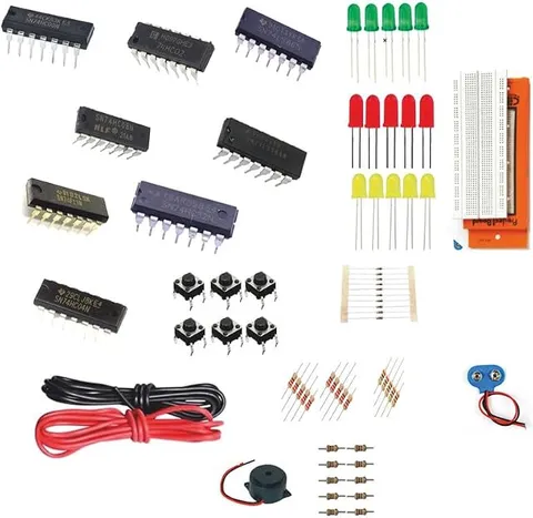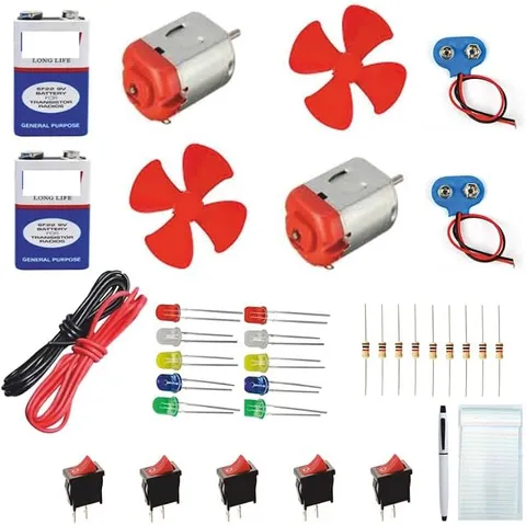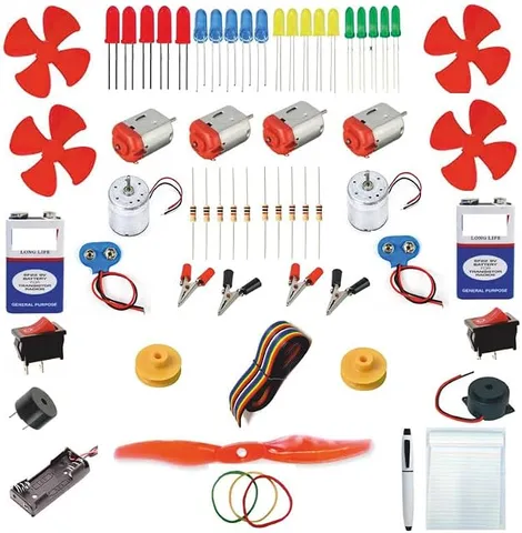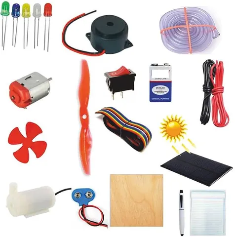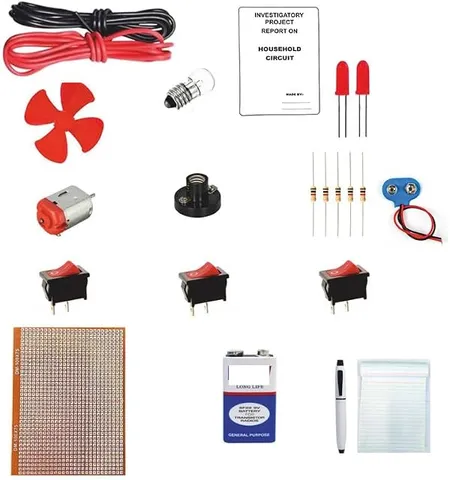
- Components and Spares
- Component
Simple Electronic Household Circuit with Zero PCB DIY KIT Electronic Components
Code B0FGV4DPV8
- Paid for and delivered by Amazon. The current price and the delivery date for your PIN code are shown there.
- Sold by Gurukul Technicals Institute, Delhi.
- Need a different topic, a custom version or a school order? Ask on WhatsApp.
In this project guide
Component
About this part
This DIY kit is for building a model of a household circuit on a zero PCB, so students learn how the switches and loads of a house are wired while practising real assembly. It turns the textbook diagram of a home circuit into something you build and test with your own hands.
How it works
The science behind it
The idea the part demonstrates, in words you can use in your report and when you explain it.
Appliances in a house are connected in parallel. Each branch gets the full supply voltage and has its own switch, so turning off the fan does not turn off the tube light. In a parallel circuit the total current from the supply is the sum of the branch currents, which is why running many appliances together draws more current from the mains. The power used in each branch is P = V × I, measured in watts. A zero PCB, also called a perfboard, is a board with a grid of holes 2.54 mm apart and no fixed tracks. Components are pushed through the holes and joined by soldering and short wire links, so the layout you plan on paper becomes a permanent circuit. A model like this should run on a low-voltage battery; real Indian homes get 230 V AC at 50 Hz, which is never used for school models.
Make it yourself
Make a household circuit on a zero PCB yourself
Everything you need and the order to do it in. Tick off the materials as you collect them.
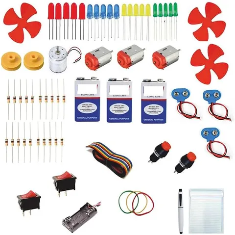
What you need 10
Step by step 9 steps
- Draw the circuit first
A main line from the battery through the fuse, then three parallel branches, each with its own switch and load.
Plan the layout on the zero PCB with a pencil: a positive rail along the top and a negative rail along the bottom, like the live and neutral lines in a house.
Solder the fuse holder and the battery snap leads at one end, with the fuse in the positive line.
Solder each switch between the positive rail and its load, so the switch breaks the positive side, just as house switches go in the live wire.
Solder each LED with its resistor (long leg towards the switch) and the motor between its switch and the negative rail.
Check every joint against your drawing, look for solder bridges between neighbouring holes, and test for shorts between the rails with a multimeter before connecting the battery.
Connect the battery and try each switch alone, then all together. Each load should work on its own without affecting the others.
Switch one branch off or unclip the motor lead to show that the other branches keep working, which is why houses are wired in parallel.
Mount the board on the house front and label each 'room' or appliance.
Read this first
Safety first
Go through these points before you build or switch anything on. Younger students should do this with an adult.
- Solder only with an adult; the iron tip is very hot, so keep it in its stand and work in an airy room.
- Trim component legs with the board pointing away from your face, because cut ends can fly.
- This model uses only a 9 V battery; never connect it or any part of it to the 230 V house supply.
- Disconnect the battery before changing any wiring.
Troubleshooting
If something does not work
The usual problems with this part and how to fix them. Open a problem to see the fix.
One branch does not work but the others do
Check that branch's switch and joints. An LED fitted backwards will not light, and a dull, lumpy solder joint may not conduct; reheat it.
Nothing works at all
Check the battery and the fuse first. A blown fuse means there was a short circuit, so look for a solder bridge between the two rails before fitting a new fuse.
The LEDs dim when the fan starts
The battery is weak. Fit a fresh one; this also shows that more loads draw more current from the supply.
One switch turns on two loads
A wire goes to the wrong point or two pads are joined by solder. Compare with your drawing and remove the bridge with the iron.
Exhibition day
How to present it
A running order for the exhibition table or the practical, step by step.
Show the circuit diagram next to the board and trace each parallel branch with your finger.
Test each branch with its own switch as soon as you finish it, and explain why testing step by step makes faults easier to find.
Point out your solder joints and explain why a shiny, cone-shaped joint is a good one.
Measure the battery voltage across each branch with a multimeter to show that every branch gets the same voltage.
Practice
Viva questions
Practice questions on this part, with short answers. Try each one aloud before you open the answer.
Why are household appliances connected in parallel?
So that each appliance gets the full supply voltage and can be switched on or off without affecting the others.
In a parallel circuit, how is the total current related to the branch currents?
The total current equals the sum of the currents in all the branches.
What is a zero PCB?
It is a general-purpose board with a grid of holes and no fixed circuit pattern, on which components are soldered and joined to make any circuit.
What are the supply voltage and frequency in Indian homes?
Homes in India get 230 V AC at a frequency of 50 Hz.
Project file
Project file outline
The headings of the project file, in order. Give each heading its own section and write it in your own words.
Free ebook: Writing a Science Project FileContents
- Aim: to build a model of household wiring on a zero PCB and show that appliances are connected in parallel
- Introduction: how electricity reaches a house and why each room has its own switches
- Materials and tools used
- Circuit diagram with the fuse, switches and three parallel branches
- Theory: parallel circuits, P = V × I, and the job of a fuse
- Procedure: planning, soldering and testing the board
- Observations: which loads work for each switch setting (table)
- Safety rules for real house wiring
- Conclusion and what was learnt about soldering
Buying checklist
Before you buy
What to check before you order the part, and what to do when it arrives.
1Before you order
- Check the listing for the parts named, and plan for a soldering iron, since a zero PCB is normally soldered.
- Make sure an adult can supervise the soldering, or ask your teacher whether the school lab can help.
- It suits the electricity chapter and practical skill activities; check it matches your class.
- Start building at least a week before submission so there is time to fix any joints.
- Check the delivery date for your PIN code on the marketplace, and order well before the exhibition or practical.
2When it arrives
- Count and sort the parts into a small box as soon as the kit arrives.
Next steps
Take it further
Ways to turn this part into a bigger investigation or a stronger exhibition entry.
Add a two-way (staircase) switch arrangement using two SPDT switches.
Measure the current in each branch with a multimeter and show that the total equals their sum.
Add a third green line on the board to show where the earth wire runs in a real house, and explain earthing on a chart.
Audience
Who it suits
Suits Class 8 to 10 students learning about electric circuits, and anyone who wants to practise soldering on a first real project.
- CategoryComponents and Spares
- TypeComponent
Free to read
Free ebooks for this topic
Free PDF ebooks from Gurukul Technicals Institute on the science, the making and the presenting of projects like this one.
- Free PDF ebook
Electronic Components Handbook
Resistors, capacitors, LEDs, diodes, transistors and more, with how to use each
- Free PDF ebook
Electricity and Magnetism Experiments
Hands-on experiments with cells, wires, bulbs and magnets
- Free PDF ebook
Your Science Exhibition Guide
Choose a project, build it, present it and answer the judges with confidence
- Free PDF ebook
Writing a Science Project File
How to write the report, from the cover page to the bibliography