- Physics
- Ready-made model
- Class 10 to 12
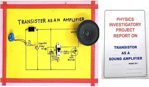
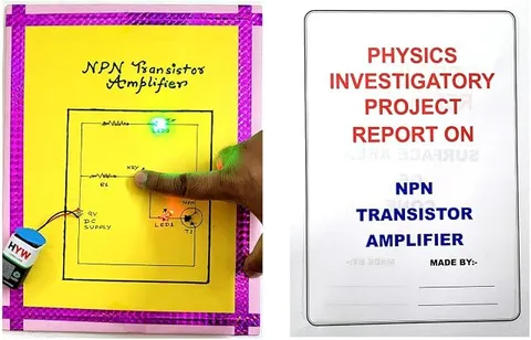
NPN Transistor as an Amplifier Working Model
Code B0G2T5Q4YT
- Paid for and delivered by Amazon. The current price and the delivery date for your PIN code are shown there.
- Sold by Gurukul Technicals Institute, Delhi.
- Need a different topic, a custom version or a school order? Ask on WhatsApp.
In this project guide
Ready-made model
About this model
This working model shows an NPN transistor used as an amplifier, where a small input signal controls a much larger output. It is the basic idea behind public address systems, radios and hearing aids, and a strong investigatory project on semiconductor devices.
What the listing says
- Physics Investigatory Project
How it works
The science behind it
The idea the model demonstrates, in words you can use in your report and when you explain it.
An NPN transistor has three regions: emitter, base and collector. To amplify, the base-emitter junction is forward biased and the collector-base junction is reverse biased. A tiny base current IB then controls a much larger collector current IC, and IE = IB + IC. The ratio β = IC/IB is the current gain. In the common-emitter amplifier, a small AC signal at the base makes IB vary a little, IC varies much more, and the collector resistor turns that change into a large voltage swing at the output. The output voltage is 180° out of phase with the input: when the input rises, the output falls. The extra energy in the output comes from the battery, not from the transistor itself. The loudspeaker systems used at Indian weddings and melas rely on amplifiers working on this same principle, only with many stages and much more power.
Make it yourself
Make an NPN transistor amplifier yourself
Build your own version from scratch, or use the steps to understand how the ready-made model is put together before you present it.
What you need 8
Step by step 8 steps
Identify the transistor's emitter, base and collector from its pin diagram and place it on the breadboard.
- Bias it
47 kΩ from positive to base, 10 kΩ from base to negative, 4.7 kΩ from positive to collector and 1 kΩ from emitter to negative.
Switch on and measure the DC voltage at the collector. It should be roughly half the battery voltage, meaning the transistor sits in the middle of its working range.
- Connect the input
The audio cable's ground to negative, and its signal wire through a 10 µF capacitor (negative leg towards the phone) to the base.
Connect a 10 µF capacitor from the collector (positive leg towards the collector) as the output, and measure between its free end and negative.
Play a steady low tone at low volume and measure the AC voltage at the input and at the output. Voltage gain = output ÷ input.
Add the 100 µF capacitor across the 1 kΩ emitter resistor (positive leg towards the emitter). The gain jumps many times, and a loud input now gets clipped. Record the new gain at a very low volume.
Mount the board with labels for input, bias, transistor and output, and draw the circuit with input and output waves 180° apart.
Read this first
Safety first
Go through these points before you build or switch anything on. Younger students should do this with an adult.
- Use only the 9 V battery; never connect the circuit to a mains adapter or a charger's insides.
- Electrolytic capacitors must go the right way round, or they can bulge or burst.
- Use an old phone or player on its own battery (not while charging), with the volume low.
- Solder only with an adult.
Troubleshooting
If something does not work
The usual problems with this model and how to fix them. Open a problem to see the fix.
The collector voltage is almost 9 V
The transistor is cut off. Check the base bias resistors and the transistor's pins; the base should be at about 1.5 V.
The collector voltage is nearly 0 V
The transistor is saturated. Check that the 10 kΩ goes from base to negative and that the emitter resistor is in place.
There is no output signal
Check the capacitors' polarity and that the audio ground is joined to negative. Measure the input to make sure a signal is arriving.
The multimeter's AC readings look wrong
Many meters read AC accurately only at low frequencies. Use a low tone, about 100 to 200 Hz, for your measurements.
Exhibition day
How to present it
A running order for the exhibition table or the practical, step by step.
Compare the sizes of the input and output signals on a chart, or on an oscilloscope if your lab has one.
Explain the biasing of both junctions with a labelled diagram.
Mention phase reversal and draw the input and output waveforms one above the other.
Point out that the extra energy comes from the battery, a common viva trap.
Practice
Viva questions
Practice questions on this model, with short answers. Try each one aloud before you open the answer.
How are the junctions biased for a transistor to work as an amplifier?
The emitter-base junction is forward biased and the collector-base junction is reverse biased.
What is the current gain β of a transistor?
It is the ratio of the collector current to the base current, β = IC/IB.
What is the phase relation between input and output in a CE amplifier?
The output voltage is 180° out of phase with the input voltage.
Write the relation between the emitter, base and collector currents.
IE = IB + IC.
Project file
Project file outline
The headings of the project file, in order. Give each heading its own section and write it in your own words.
Free ebook: Writing a Science Project FileContents
- Aim: to study an NPN transistor as a common-emitter amplifier
- Introduction: semiconductors and the invention of the transistor
- Materials and circuit diagram of the common-emitter stage
- Theory: biasing, IE = IB + IC, and current gain β = IC / IB
- Voltage gain and the 180° phase reversal
- Procedure: setting the bias and measuring the gain
- Observations: DC voltages at base, emitter and collector, and AC input and output voltages with and without the bypass capacitor (table)
- Applications: radios, public address systems and hearing aids
- Conclusion, precautions and sources of error in the gain readings
Buying checklist
Before you buy
What to check before you order the model, and what to do when it arrives.
1Before you order
- The transistor amplifier is a Class 12 semiconductor topic; check it matches your syllabus and practical list.
- Read the listing for how the input signal is given (microphone, audio lead or switch) and what power it needs.
- Learn the circuit diagram and the reason for the 180° phase difference, as these are common viva questions.
- Keep the box to protect the components.
- Check the delivery date for your PIN code on the marketplace, and order well before the exhibition or practical.
2When it arrives
- On arrival, test it with a signal source, and again a few days before the practical.
Next steps
Take it further
Ways to turn this model into a bigger investigation or a stronger exhibition entry.
Measure IB and IC with a multimeter at different bias points and calculate β.
Use an oscilloscope in the school lab to show the input and output waves 180° apart.
Add a second stage and compare the overall gain with the product of the two single-stage gains.
Audience
Who it suits
Suits Class 12 physics investigatory projects on semiconductor electronics, and diploma or engineering analog electronics labs.
- ClassClass 10 to 12
- SubjectPhysics
- TypeReady-made model
Free to read
Free ebooks for this topic
Free PDF ebooks from Gurukul Technicals Institute on the science, the making and the presenting of projects like this one.
- Free PDF ebook
Physics Working Models Explained
Twenty classic models, how each works and how to make it
- Free PDF ebook
Investigatory Projects for Class 11 and 12
Topics, method and report structure for physics, chemistry and biology
- Free PDF ebook
Your Science Exhibition Guide
Choose a project, build it, present it and answer the judges with confidence
- Free PDF ebook
Writing a Science Project File
How to write the report, from the cover page to the bibliography