- Physics
- Ready-made model
- Class 10 to 12
NOR Gate Using Transistor Logic Gate Physics Investigatory Project
Code B0G2TC5FMB
- Paid for and delivered by Amazon. The current price and the delivery date for your PIN code are shown there.
- Sold by Gurukul Technicals Institute, Delhi.
- Need a different topic, a custom version or a school order? Ask on WhatsApp.
In this project guide
Ready-made model
About this model
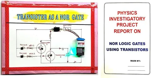
This project builds a NOR logic gate from transistors, showing how the basic decisions inside every computer chip are made with simple switches. Students can set the inputs and watch the output follow the NOR truth table. It is a good bridge between semiconductor physics and Boolean logic in computer science.
How it works
The science behind it
The idea the model demonstrates, in words you can use in your report and when you explain it.
A NOR gate is an OR gate followed by a NOT gate. Its output is 1 (high) only when all inputs are 0 (low); if any input is 1, the output is 0. In Boolean algebra this is written Y = (A + B)', the complement of A OR B. In a transistor version, two NPN transistors are connected in parallel between the output and ground, sharing one collector resistor. When an input is high, its transistor turns on and pulls the output down to nearly 0 V. Only when both inputs are low are both transistors off, and the output rises to the supply voltage through the resistor. NOR is called a universal gate because NOT, OR, AND and every other gate can be built from NOR gates alone; joining both inputs together, for example, gives a NOT gate. The Apollo Guidance Computer that flew to the Moon was built almost entirely from NOR gates.
Make it yourself
Make a NOR gate from transistors yourself
Build your own version from scratch, or use the steps to understand how the ready-made model is put together before you present it.
What you need 8
Step by step 8 steps
Place both transistors on the breadboard with their emitters joined to negative and their collectors joined together. This shared collector point is the output, Y.
Connect Y to positive through the 470 Ω collector resistor.
Connect the red output LED with its 470 Ω resistor from Y to negative, long leg towards Y.
- Wire input A
A switch from positive to an input line, a 10 kΩ pull-down from that line to negative, a green LED with 1 kΩ from the line to negative, and a 10 kΩ resistor from the line to the first transistor's base. Repeat for input B and the second transistor.
Switch on with both inputs off: the output LED should glow, meaning Y = 1.
Turn on A, then B, then both. The output LED should go off in every one of these cases.
Fill in the truth table (00 gives 1, 01 gives 0, 10 gives 0, 11 gives 0) and compare it with Y = (A + B)'.
Mount the board neatly, label A, B and Y, and draw the circuit diagram beside it.
Read this first
Safety first
Go through these points before you build or switch anything on. Younger students should do this with an adult.
- Use cells only; never an adapter you have opened or modified.
- Every LED and every transistor base needs its resistor, or parts may overheat.
- If you solder the final board, do it with an adult.
- Take the cells out when the model is stored.
Troubleshooting
If something does not work
The usual problems with this model and how to fix them. Open a problem to see the fix.
The output LED never lights
A transistor may be stuck on. Check that the pull-down resistors are fitted so the inputs fall to 0 when switched off, and that collector and emitter are not swapped.
The output LED stays on when an input is on
That input's transistor is not switching. Check its base resistor, and check that the switch really connects the line to positive.
The output LED is very dim
Use fresh cells, or slightly smaller collector and LED resistors (not below 220 Ω).
An input LED glows faintly with its switch off
The switch may be wired to the wrong pins so it never fully opens, or a stray wire or solder bridge touches positive. Check the switch with continuity mode in both positions.
Exhibition day
How to present it
A running order for the exhibition table or the practical, step by step.
Go through all four input combinations in order (00, 01, 10, 11) and let the judge tick the truth table.
Explain why the output is high only for 00, using the two transistors as switches.
Show how joining both inputs turns it into a NOT gate, which proves it is universal.
Write the Boolean expression and the truth table neatly on a card beside the model.
Practice
Viva questions
Practice questions on this model, with short answers. Try each one aloud before you open the answer.
What is the Boolean expression for a NOR gate?
Y = (A + B)', which means the output is the complement of A OR B.
Why is NOR called a universal gate?
Because any other logic gate, such as NOT, AND or OR, can be made using only NOR gates.
How do you get a NOT gate from a NOR gate?
Join both inputs together; then an input of 0 gives 1 and an input of 1 gives 0.
In the transistor circuit, why does the output go low when any input is high?
A high input turns its transistor on, which connects the output to ground.
Project file
Project file outline
The headings of the project file, in order. Give each heading its own section and write it in your own words.
Free ebook: Writing a Science Project FileContents
- Aim: to construct a NOR gate using transistors and verify its truth table
- Introduction: logic gates and digital signals (1 and 0)
- Materials and circuit diagram of the two-transistor NOR gate
- Theory: the Boolean expression Y = (A + B)' and the transistor as a switch
- Procedure: wiring the inputs, transistors and output LED
- Truth table: expected and observed outputs
- NOR as a universal gate: making NOT, OR and AND from NOR gates
- Applications in computers and control circuits
- Conclusion and precautions for handling transistors
Buying checklist
Before you buy
What to check before you order the model, and what to do when it arrives.
1Before you order
- Check that it matches your Class 12 semiconductor electronics syllabus or your computer science logic chapter.
- Read the listing to see whether batteries and a report are included.
- Learn the truth table well; viva questions usually start there.
- Keep the box to protect the switches.
- Check the delivery date for your PIN code on the marketplace, and order well before the exhibition or practical.
2When it arrives
- Test all four input combinations on arrival and again a few days before the exhibition.
Next steps
Take it further
Ways to turn this model into a bigger investigation or a stronger exhibition entry.
Join NOR gates to make OR (two gates) and AND (three gates) circuits, proving that NOR is universal.
Build an SR latch from two NOR gates, a one-bit memory.
Measure the output voltage for each input combination and define the 'high' and 'low' levels.
Audience
Who it suits
Suits Class 11 and 12 students for physics investigatory projects and Boolean logic in computer science, and diploma digital electronics labs.
- ClassClass 10 to 12
- SubjectPhysics
- TypeReady-made model
Free to read
Free ebooks for this topic
Free PDF ebooks from Gurukul Technicals Institute on the science, the making and the presenting of projects like this one.
- Free PDF ebook
Physics Working Models Explained
Twenty classic models, how each works and how to make it
- Free PDF ebook
Investigatory Projects for Class 11 and 12
Topics, method and report structure for physics, chemistry and biology
- Free PDF ebook
Your Science Exhibition Guide
Choose a project, build it, present it and answer the judges with confidence