- Physics
- Ready-made model
- Class 10 to 12
NAND Gate Using Transistor Logic Gate Physics Investigatory Project
Code B0G2T6YNR3
- Paid for and delivered by Amazon. The current price and the delivery date for your PIN code are shown there.
- Sold by Gurukul Technicals Institute, Delhi.
- Need a different topic, a custom version or a school order? Ask on WhatsApp.
In this project guide
Ready-made model
About this model
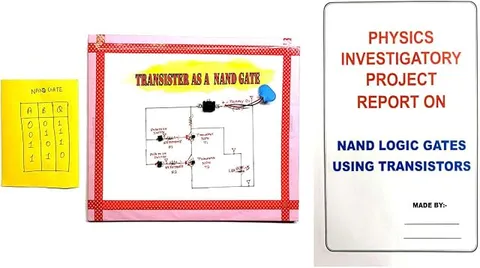
This investigatory project builds a NAND logic gate from transistors, showing what happens inside a logic gate instead of treating it as a black box. It connects the switching action of a transistor directly to the NAND truth table.
How it works
The science behind it
The idea the model demonstrates, in words you can use in your report and when you explain it.
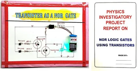
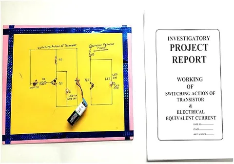
A transistor works as a switch: off with no base current, and saturated, almost like a closed switch, with enough base current. A NAND gate can be built from two NPN transistors connected in series between the output point and ground, with a resistor from the output to the positive supply. Each input drives the base of one transistor through its own resistor. If either input is 0, that transistor is off, the series path to ground is broken, and the resistor pulls the output up to HIGH (1). Only when both inputs are 1 do both transistors turn on together, connecting the output to ground and making it LOW (0). This gives exactly the NAND truth table, Y = (A · B)′. Placing the two transistors in parallel instead would make a NOR gate, because then either transistor alone could pull the output low. Real logic chips contain millions of transistors switching in just this way.
Make it yourself
Make a NAND gate from two transistors yourself
Build your own version from scratch, or use the steps to understand how the ready-made model is put together before you present it.
What you need 10
Step by step 8 steps
- Identify each BC547's legs
With the flat face towards you, they are collector, base and emitter from left to right.
Connect the 1 kΩ resistor from the positive line to an output point, and the collector of the first transistor (T1) to that output point.
Join T1's emitter to the second transistor's (T2's) collector, and T2's emitter to negative, so the two transistors are in series between the output and negative.
Connect input switch A to T1's base through a 10 kΩ resistor, and switch B to T2's base through the other. Each switch's middle terminal goes to its resistor, one end to positive and the other to negative, so no input is ever left floating.
Add a green LED with its 1 kΩ resistor from each switch's middle terminal to negative, so it lights when that input is 1.
Connect the red LED with its 470 Ω resistor from the output point to negative.
Set the four input combinations and record the red LED and the output voltage each time: the LED should go out only when both inputs are 1.
With both inputs at 1, measure the collector-to-emitter voltage of each transistor to show that both are fully on, like closed switches in series.
Read this first
Safety first
Go through these points before you build or switch anything on. Younger students should do this with an adult.
- Always keep the 10 kΩ resistors in the base leads; without them the transistors draw too much base current and can be damaged.
- Keep the 470 Ω resistor in series with the output LED, and use only the 9 V battery.
- Switch off at once if a transistor gets warm, and check its legs before trying again.
- Use the soldering iron only with an adult and rest it in its stand.
Troubleshooting
If something does not work
The usual problems with this model and how to fix them. Open a problem to see the fix.
The output LED never goes out
One transistor is not turning on: its legs may be mixed up, its base resistor loose, or its input not reaching positive. With that input at 1, the base should read about 0.7 V above the emitter.
The output LED goes out when only one input is 1
The transistors have been wired side by side (in parallel) instead of in series, which makes a NOR gate, or one transistor is damaged and conducts all the time. Check the series connection from T1's emitter to T2's collector.
The output LED is dim even when it should be on
The LED and the 1 kΩ pull-up share the voltage, so the output 'high' sits at a few volts. This is normal; use a 470 Ω pull-up for a brighter LED and note the output voltage in your table.
The input LEDs work but the output never changes
The series chain is broken, for example T2's emitter is not connected to negative. Trace the path from the output point through both transistors to negative.
Exhibition day
How to present it
A running order for the exhibition table or the practical, step by step.
Show each of the four input combinations and say which transistors are on for each.
Draw the circuit with the two transistors in series and trace the path to ground.
Explain how changing the series connection to parallel would make a NOR gate.
Keep the NAND truth table beside the model so the examiner can check each row.
Practice
Viva questions
Practice questions on this model, with short answers. Try each one aloud before you open the answer.
Why are the two transistors connected in series for a NAND gate?
So that the output is pulled LOW only when both transistors are on, which happens only when both inputs are HIGH.
What is the job of the resistor between the output and the supply?
It pulls the output up to HIGH whenever the transistor path to ground is broken.
In which states does a transistor work inside a logic gate?
Cut-off (off) and saturation (on), so it acts as a switch rather than an amplifier.
Which gate do you get if the two transistors are connected in parallel?
A NOR gate.
Project file
Project file outline
The headings of the project file, in order. Give each heading its own section and write it in your own words.
Free ebook: Writing a Science Project FileContents
- Aim: to build a NAND gate from transistors and verify its truth table
- Introduction: logic gates as switches working on 0 and 1
- The transistor as a switch: cut-off and saturation
- Circuit: two transistors in series with a pull-up resistor
- Working of the circuit for each of the four input combinations
- Observations: output LED and output voltage for each combination
- Why NAND is called a universal gate
- Comparison with the NAND gate chips used in computers
- Conclusion and bibliography
Buying checklist
Before you buy
What to check before you order the model, and what to do when it arrives.
1Before you order
- Check with your teacher that logic gates or transistor switching are part of your current syllabus.
- Read the listing to see how the inputs are set and what powers the board.
- Practise explaining, using the idea of switches in series, why the output is 0 only when both transistors are on.
- Keep the box for transport.
- Check the delivery date for your PIN code on the marketplace, and order well before the exhibition or practical.
2When it arrives
- Go through all four input combinations as soon as it arrives and note the output each time.
Next steps
Take it further
Ways to turn this model into a bigger investigation or a stronger exhibition entry.
Rewire the two transistors in parallel to make a NOR gate, and compare the two truth tables.
Build a one-transistor NOT gate and add it after your NAND gate to make an AND gate.
Feed one input from a potentiometer and find the input voltage at which the output switches.
Audience
Who it suits
Class 11 and 12 physics students and electronics learners who want to understand logic gates at the transistor level.
- ClassClass 10 to 12
- SubjectPhysics
- TypeReady-made model
Free to read
Free ebooks for this topic
Free PDF ebooks from Gurukul Technicals Institute on the science, the making and the presenting of projects like this one.
- Free PDF ebook
Physics Working Models Explained
Twenty classic models, how each works and how to make it
- Free PDF ebook
Investigatory Projects for Class 11 and 12
Topics, method and report structure for physics, chemistry and biology
- Free PDF ebook
Your Science Exhibition Guide
Choose a project, build it, present it and answer the judges with confidence