- Physics
- Ready-made model
- Class 10 to 12
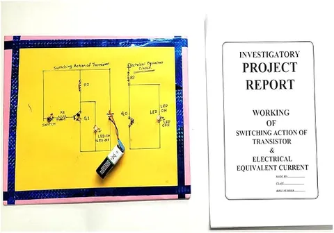
Switching Action of Transistor and Electrical Equivalent Current Physics Investigatory Project and Model
Code B0C3H5Y2P8
- Paid for and delivered by Amazon. The current price and the delivery date for your PIN code are shown there.
- Sold by Gurukul Technicals Institute, Delhi.
- Need a different topic, a custom version or a school order? Ask on WhatsApp.
In this project guide
Ready-made model
About this model
This investigatory model demonstrates how a transistor works as an electronic switch, turning a load fully on or fully off with a small control current. It is useful for showing the electrical equivalent of a transistor in its two switching states, an open switch and a closed switch.
How it works
The science behind it
The idea the model demonstrates, in words you can use in your report and when you explain it.
A transistor used as a switch works in two regions. In cut-off, the base-emitter voltage is below about 0.7 V (for silicon), almost no base current flows and the collector current is nearly zero, so the transistor behaves like an open switch. In saturation, so much base current flows that the collector current is limited only by the load, and the voltage between collector and emitter falls to roughly 0.1 to 0.3 V, so the transistor behaves like a closed switch. Between the two lies the active region, where IC = β × IB and the transistor amplifies instead. The key idea is control: a base current of a fraction of a milliampere can switch a collector current many times larger. A resistor in the base lead limits that current and protects the junction. This is how a weak sensor signal can switch on a relay, buzzer or lamp.
Make it yourself
Make a transistor switching action model yourself
Build your own version from scratch, or use the steps to understand how the ready-made model is put together before you present it.
What you need 9
Step by step 8 steps
Divide the board into two halves: the transistor circuit on the left and its electrical equivalent, an ordinary switch, on the right.
- Left side
Connect an LED and its 330 Ω resistor from the positive rail to the transistor's collector, and the emitter to negative.
Feed the base from the positive rail through the push button, the 10 kΩ resistor and the potentiometer in series.
- Right side
Connect the second LED and its resistor in series with the toggle switch across the same supply.
With the button released, measure the collector-emitter voltage: it is most of the supply voltage, the same as across the open toggle switch.
Press the button with the potentiometer at its lowest value: the LED lights and the collector-emitter voltage falls to a few tenths of a volt, like a closed switch.
Measure the base current and the collector current in the on state, and show that a tiny base current controls a much larger collector current.
Keep the button pressed and turn the potentiometer up slowly: the LED dims gradually, because between cut-off and saturation the transistor is in its active region, where it amplifies instead of switching.
Read this first
Safety first
Go through these points before you build or switch anything on. Younger students should do this with an adult.
- Use only the 6 V cell pack; this demonstration must not switch any mains device.
- Keep the 10 kΩ resistor in series with the potentiometer, so the base current stays safe even at the lowest setting.
- When measuring current, put the multimeter in series and on a current range; connecting it across the supply on that range can blow its fuse.
- Solder only with an adult.
Troubleshooting
If something does not work
The usual problems with this model and how to fix them. Open a problem to see the fix.
The transistor's LED stays on with the button released
The transistor may be shorted, or the button is wired so it is always closed. Test the transistor with a multimeter and recheck which legs of the button connect.
The LED never lights
Check the transistor's pin order, the LED's direction, and that the base circuit really reaches the positive rail when the button is pressed.
The collector-emitter voltage stays high while the LED is on
The transistor is not saturated because the base current is too small. Turn the potentiometer to its lowest value and check the 10 kΩ resistor.
The meter shows zero current
The red probe may be in the wrong socket or the meter's fuse may have blown. Move the probe to the mA socket and check the fuse.
Exhibition day
How to present it
A running order for the exhibition table or the practical, step by step.
Draw the two equivalent circuits, an open switch and a closed switch, next to the model.
If a multimeter is allowed, measure the collector-emitter voltage in the off and on states.
Explain how a small base current controls a much larger collector current.
Mention real uses, such as a sensor switching a relay or buzzer through a transistor.
Practice
Viva questions
Practice questions on this model, with short answers. Try each one aloud before you open the answer.
In which two regions does a transistor work as a switch?
Cut-off, where it is off like an open switch, and saturation, where it is on like a closed switch.
Why is a resistor connected in series with the base?
To limit the base current so that the base-emitter junction is not damaged.
What base-emitter voltage does a silicon transistor need to start conducting?
About 0.6 to 0.7 V.
What happens in the active region?
The collector current is proportional to the base current (IC = β × IB), so the transistor works as an amplifier rather than a switch.
Project file
Project file outline
The headings of the project file, in order. Give each heading its own section and write it in your own words.
Free ebook: Writing a Science Project FileContents
- Aim: to show how a transistor works as a switch and compare it with an ordinary switch
- The NPN transistor and its three regions: cut-off, active and saturation
- Circuit diagrams of the transistor switch and of its electrical equivalent
- Construction of the two-sided board
- Observation table: base current, collector current, VBE and VCE in the off and on states
- Comparison with the voltage across an open and a closed switch
- The active region and why the LED dims
- Uses of transistor switches in computers, relays and automatic circuits
- Conclusion and precautions
Buying checklist
Before you buy
What to check before you order the model, and what to do when it arrives.
1Before you order
- Check that a transistor-as-a-switch project suits your class and the chapter on semiconductor devices.
- Read the listing for the supply needed and anything else it mentions; do not assume a battery or a report is included.
- Test it a few days before the exhibition and carry spare cells.
- Keep the box so the board travels safely.
- Check the delivery date for your PIN code on the marketplace, and order well before the exhibition or practical.
- Practise explaining it. Judges ask what the model shows and why; knowing the science matters as much as the model. The viva questions above are a good place to start.
2When it arrives
- When it arrives, take your own readings of the voltages in both states, as examiners like to see measured values.
Next steps
Take it further
Ways to turn this model into a bigger investigation or a stronger exhibition entry.
Plot collector current against base current to find the current gain β, and mark where the transistor saturates.
Use the transistor switch to drive a small relay, and explain why the relay coil needs a protection diode.
Replace the button with an LDR or a thermistor divider to make an automatic switch for light or heat.
Audience
Who it suits
Class 11 and 12 physics investigatory projects, and first-year electronics students learning transistor basics.
- ClassClass 10 to 12
- SubjectPhysics
- TypeReady-made model
Free to read
Free ebooks for this topic
Free PDF ebooks from Gurukul Technicals Institute on the science, the making and the presenting of projects like this one.
- Free PDF ebook
Electricity and Magnetism Experiments
Hands-on experiments with cells, wires, bulbs and magnets
- Free PDF ebook
Physics Working Models Explained
Twenty classic models, how each works and how to make it
- Free PDF ebook
Investigatory Projects for Class 11 and 12
Topics, method and report structure for physics, chemistry and biology
- Free PDF ebook
Your Science Exhibition Guide
Choose a project, build it, present it and answer the judges with confidence