- Physics
- Ready-made model
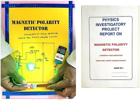
Magnet Polarity Detector Using Hall Effect Sensor Project Model Educational Electronic Hobby Kit
Code B0DTYK9XXC
- Paid for and delivered by Amazon. The current price and the delivery date for your PIN code are shown there.
- Sold by Gurukul Technicals Institute, Delhi.
- Need a different topic, a custom version or a school order? Ask on WhatsApp.
In this project guide
Ready-made model
About this model
An electronic hobby kit that uses a Hall effect sensor to tell the north pole of a magnet from the south pole. It turns an invisible magnetic field into a clear signal and introduces students to one of the most widely used sensors in modern electronics.
How it works
The science behind it
The idea the model demonstrates, in words you can use in your report and when you explain it.
The Hall effect was discovered by Edwin Hall in 1879. When a current flows through a thin strip of conductor or semiconductor placed in a magnetic field at right angles to it, the moving charge carriers feel a sideways magnetic force, the Lorentz force, of size F = qvB. They are pushed towards one edge of the strip, so a small voltage, the Hall voltage, appears across the strip at right angles to both the current and the field. If the field is reversed, the carriers are pushed to the opposite edge and the Hall voltage changes sign. A Hall sensor chip amplifies this tiny voltage, and the circuit uses its sign to decide whether a north or a south pole is facing the sensor. No contact with the magnet is needed. The twist throttle of an electric scooter or e-rickshaw commonly uses a Hall sensor and a small magnet in the same way.
Make it yourself
Make a magnet polarity detector with a Hall sensor yourself
Build your own version from scratch, or use the steps to understand how the ready-made model is put together before you present it.
What you need 10
Step by step 8 steps
Power the sensor alone from the 5 V supply and measure its output with no magnet nearby: it sits at about half the supply, around 2.5 V.
Bring one pole of the magnet towards the sensor's face: the output rises. Turn the magnet round and the other pole makes it fall. Note which pole does which for your sensor.
Check the magnet's poles with the compass: the north end of the compass needle points to the magnet's south pole.
Wire each preset as a voltage divider across the supply, and set one about 0.3 V above the no-magnet output (upper level) and the other about 0.3 V below it (lower level).
- First comparator
Sensor output to pin 3, upper level to pin 2, and output pin 1 through 330 Ω to the LED for the pole that raises the voltage. Connect the LM358's pin 8 to 5 V and pin 4 to ground.
- Second comparator
Lower level to pin 5, sensor output to pin 6, and output pin 7 through 330 Ω to the LED for the pole that lowers the voltage.
Bring each pole towards the sensor: one LED lights for north, the other for south, and neither lights with no magnet nearby.
Fit the sensor at the end of the box with its face outward, mount the LEDs labelled N and S, and test unknown magnets such as fridge magnets.
Read this first
Safety first
Go through these points before you build or switch anything on. Younger students should do this with an adult.
- Keep strong magnets away from phones, bank cards, watches and screens, and away from anyone with a pacemaker.
- Strong magnets can snap together and pinch fingers; slide them apart rather than pulling.
- Keep small magnets away from young children, as swallowed magnets are very dangerous.
- Use the soldering iron only with an adult, and power the circuit only from the battery and regulator or the cell pack.
Troubleshooting
If something does not work
The usual problems with this model and how to fix them. Open a problem to see the fix.
Only one pole is ever detected
You may have a switching Hall sensor (such as the 3144 type), which responds to one pole only. Use a linear 49E-type sensor, and check that the lower preset is set below the no-magnet voltage.
An LED stays on with no magnet nearby
Its preset is too close to the sensor's resting voltage, or a steel object is close by. Move magnets and steel away, then reset the presets about 0.3 V either side.
Nothing changes when a magnet comes close
The sensor's pins may be in the wrong order or the magnet is facing its back. Check the pin diagram and bring the magnet to the flat face with the markings.
The detector says north where the compass says south
The LED labels are the wrong way round for your sensor. Swap the labels; the compass is the trusted reference.
Exhibition day
How to present it
A running order for the exhibition table or the practical, step by step.
Bring each pole of a magnet towards the sensor in turn and show the different response for north and south.
Use a magnetic compass to confirm which pole is north before you start, so your result can be checked.
Show that the sensor responds without touching the magnet, and that the response stops as the magnet moves away.
Draw the Hall strip with the current, the field and the Hall voltage marked at right angles to one another.
Practice
Viva questions
Practice questions on this model, with short answers. Try each one aloud before you open the answer.
What is the Hall effect?
When a current-carrying conductor is placed in a perpendicular magnetic field, a voltage develops across it at right angles to both the current and the field.
Why does the Hall voltage change sign when the magnet is flipped?
Reversing the field reverses the magnetic force on the charge carriers, so they collect on the opposite edge of the strip.
Which force acts on the charge carriers in a Hall sensor?
The magnetic part of the Lorentz force, of size qvB when the velocity is perpendicular to the field.
Give one everyday use of Hall sensors.
They are used in electric scooter throttles, wheel speed sensors and phone flip covers to detect a magnet without contact.
Project file
Project file outline
The headings of the project file, in order. Give each heading its own section and write it in your own words.
Free ebook: Writing a Science Project FileContents
- Aim: to identify the north and south poles of a magnet using a Hall effect sensor
- Introduction: magnetic fields and poles
- The Hall effect: the Lorentz force and the Hall voltage
- The linear Hall sensor and its output
- The LM358 window comparator, with circuit diagram
- Construction and setting the trigger levels
- Observations: sensor voltage at different distances from each pole, and LED results
- Applications: speed sensors, phone covers, brushless motors and current meters
- Conclusion and bibliography
Buying checklist
Before you buy
What to check before you order the model, and what to do when it arrives.
1Before you order
- Check that magnetism and moving charges in a magnetic field fit your syllabus; the Hall effect is usually explained in higher classes, so plan your explanation for your level.
- Read the listing to see how the kit is powered and whether it needs assembly, so you can arrange a battery and tools.
- Keep a labelled magnet with the project for the exhibition, since visitors will want to try it.
- Keep the box for transport.
- Check the delivery date for your PIN code on the marketplace, and order well before the exhibition or practical.
2When it arrives
- Test it on arrival with a magnet whose poles you have checked with a compass.
Next steps
Take it further
Ways to turn this model into a bigger investigation or a stronger exhibition entry.
Record the sensor's output at 1 cm steps from each pole and plot how the field weakens with distance.
Use a microcontroller board to show the field strength as a bar on a display and the pole as N or S.
Fix a magnet to a wheel and use the sensor to count turns and work out the wheel's speed, as a bicycle speedometer does.
Audience
Who it suits
Suits Class 10 to 12 physics investigatory projects on magnetism and electronics hobbyists starting with sensors.
- SubjectPhysics
- TypeReady-made model
Free to read
Free ebooks for this topic
Free PDF ebooks from Gurukul Technicals Institute on the science, the making and the presenting of projects like this one.
- Free PDF ebook
Electricity and Magnetism Experiments
Hands-on experiments with cells, wires, bulbs and magnets
- Free PDF ebook
Physics Working Models Explained
Twenty classic models, how each works and how to make it
- Free PDF ebook
Your Science Exhibition Guide
Choose a project, build it, present it and answer the judges with confidence
- Free PDF ebook
Writing a Science Project File
How to write the report, from the cover page to the bibliography