- Components and Spares
- Component
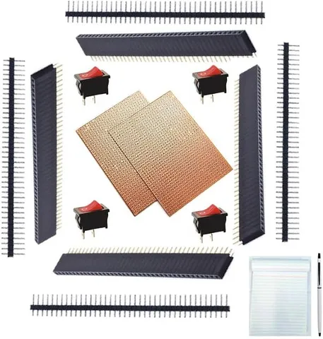
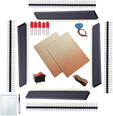
Berg Strip Male & Female DIY Kit
Code B0FGV37BQJ
- Paid for and delivered by Amazon. The current price and the delivery date for your PIN code are shown there.
- Sold by Gurukul Technicals Institute, Delhi.
- Need a different topic, a custom version or a school order? Ask on WhatsApp.
Component
About this part
A DIY kit of male and female berg strips with a zero PCB, which the listing describes as 15 components. Berg strips are the header pins and sockets used to make neat, removable connections in electronics projects, and a zero PCB is the board on which a circuit is soldered permanently.
What the listing says
- 15 Components
- Free Pen & Pad
How it works
The science behind it
The idea the part demonstrates, in words you can use in your report and when you explain it.
Berg strips, also called header pins, are rows of metal pins in a plastic holder with a standard spacing of 2.54 mm, or 0.1 inch. Male strips carry exposed pins and female strips carry matching sockets, so a module such as a sensor or a microcontroller board can be plugged in and removed without desoldering. Breadboards, jumper wires and most through-hole chips share this spacing, so they all fit together. A zero PCB, or general purpose board, has a grid of holes at this spacing, each with a copper pad, and components are soldered onto it and joined with wire or solder tracks. Solder is an alloy with a low melting point, traditionally tin and lead and now often lead-free, which flows into the joint and makes a good electrical connection. Flux in the solder removes the oxide layer from the metal so the solder can stick. Mobile repair shops across India rely on these same soldering skills.
Using it in your projects
Using berg strips and a zero PCB in your projects
What this part is good for, what else you need with it and how to connect it.
Projects you can build with it 7
- A plug-in board for an infrared sensor in an automatic hand sanitiser model
- A soil moisture alarm board for a smart garden model
- A removable sensor or display board for a microcontroller project
- A quick-change battery connector made from a 2-pin male header
- A plug-in LED bar for a water level indicator
- A permanent version of a breadboard circuit, such as a 555 flasher with its IC in a socket
- Test pins where a multimeter can be clipped on during an exhibition
What else you need 9
How to connect it 8 steps
Plan the layout on squared paper, where each square is one 2.54 mm hole: mark where the female header for the module, the LED and the power and signal pins will go.
If the board is bigger than you need, an adult scores it along a row of holes on both sides with the craft knife and snaps it over a table edge.
Break the male strips at the notches with pliers. Cut the female strip through the socket just after the last one you need, and file the cut end smooth.
Push the female header into the board from the top, turn it over, and solder just one pin. Check that the header stands straight, then solder the rest.
Solder a 2-pin male header for the cells, a 3-pin male header for the module's outputs, and the LED with its resistor between the + line and the module's OUT pin; on most of these modules OUT goes low when they sense something, which lights the LED.
Join the pins on the back with lengths of bare tinned wire soldered at each pad, taking care not to bridge neighbouring rows.
Check every track with the continuity setting, and make sure there is no short between the + and − pins.
Plug the module into the female header, connect the cell holder's leads to the 2-pin male header with female jumper wires, and test it.
Read this first
Safety first
Go through these points before you build or switch anything on. Younger students should do this with an adult.
- Solder only with an adult present, rest the iron in its stand, and work where there is fresh air.
- Wash your hands after soldering, especially if the solder contains lead.
- Snap the board over paper, wipe up the dust, and do not breathe it in.
- When cutting strips or trimming legs, hold the loose piece so it cannot fly towards your eyes.
Troubleshooting
If something does not work
The usual problems with this part and how to fix them. Open a problem to see the fix.
The solder forms a ball and will not stick to the pad
The pad is dirty or tarnished, or it is not being heated. Clean it with an eraser or fine sandpaper, and hold the iron on the pad and the pin together for two or three seconds before feeding in solder.
A pin melted its plastic holder and tilted
It was heated for too long. Make each joint quickly and let neighbouring pins cool between joints.
Two tracks are joined by solder
Remove the bridge with the desoldering wick or pump, then check the two tracks again with the continuity setting.
The module works on a breadboard but not on your board
The pin order is probably different. Compare the VCC, GND and OUT labels on the module with your board before powering it, as reversing the supply can damage the module.
Exhibition day
How to present it
A running order for the exhibition table or the practical, step by step.
Plug a module into female headers and then remove it, to show why removable connections help in testing.
Display a good solder joint and explain what makes it good: shiny, cone-shaped and covering the pad.
Move a circuit from breadboard to zero PCB and explain each step of the transfer.
Talk about soldering safety: keep the iron on a stand, work in an airy place and wash hands after handling solder.
Practice
Viva questions
Practice questions on this part, with short answers. Try each one aloud before you open the answer.
What is the standard spacing of berg strip pins?
The standard pitch is 2.54 mm, which is 0.1 inch, the same as breadboards and most through-hole ICs.
What is the difference between a breadboard and a zero PCB?
A breadboard allows temporary connections without soldering, while a zero PCB is used for permanent soldered circuits.
Why is flux used in soldering?
Flux removes the oxide layer from the metal surfaces so that molten solder can wet them and form a strong joint.
Why are female headers used for modules?
They let a module be plugged in and removed easily, so it can be replaced or reused without desoldering.
Buying checklist
Before you buy
What to check before you order the part, and what to do when it arrives.
1Before you order
- Read the listing for the number of strips, their pin counts and the size of the zero PCB, and check that the pitch is 2.54 mm.
- Berg strips have to be soldered, so plan for a soldering iron and an adult to help.
- Check that the female strips have enough sockets for your module's pins.
- Keep the cut pieces and loose pins in a small box.
- Check the delivery date for your PIN code on the marketplace, and order well before the exhibition or practical.
2When it arrives
- On arrival, check that the pins are straight and the PCB's copper pads are clean.
Next steps
Take it further
Ways to turn this part into a bigger investigation or a stronger exhibition entry.
Make your own plug-in board for a microcontroller, with headers matching its pins and sockets for your sensors.
Draw a neat layout diagram of your board for the project file, showing the front and the back.
Design the same circuit as a printed circuit board in free PCB design software and compare it with your hand-wired version.
Audience
Who it suits
Suits Class 9 to 12 electronics and robotics projects, Atal Tinkering Labs and engineering students moving from breadboard to soldered circuits.
- CategoryComponents and Spares
- TypeComponent
Free to read
Free ebooks for this topic
Free PDF ebooks from Gurukul Technicals Institute on the science, the making and the presenting of projects like this one.
- Free PDF ebook
Electronic Components Handbook
Resistors, capacitors, LEDs, diodes, transistors and more, with how to use each
- Free PDF ebook
Your Science Exhibition Guide
Choose a project, build it, present it and answer the judges with confidence
- Free PDF ebook
Writing a Science Project File
How to write the report, from the cover page to the bibliography
- Free PDF ebook
Viva Questions for Science Projects
How to answer examiner questions, with sample questions for popular projects