 50% off
- Physics
- Ready-made model
- Class 10 to 12
- Printed report included
Using Zener as a Diode Circuit Physics Working Model Educational Investigatory Project
Code B0BN2DQ5FF
- Paid for and delivered by Amazon or Flipkart. The current price and the delivery date for your PIN code are shown there.
- Sold by Gurukul Technicals Institute, Delhi.
- Need a different topic, a custom version or a school order? Ask on WhatsApp.
In this project guide
Ready-made model
About this model
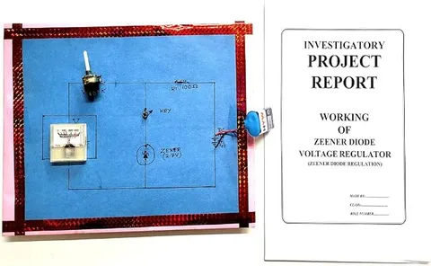
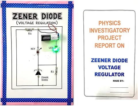
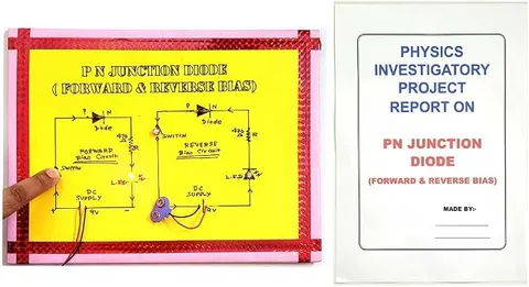
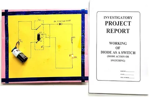
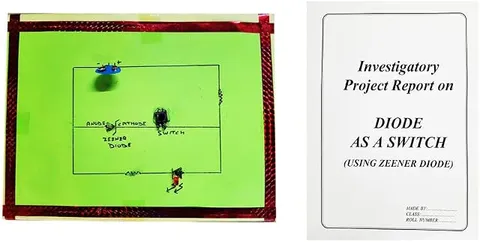
This physics investigatory model shows a Zener diode used as a switch. On a board with the circuit drawn in marker, a 9 V battery feeds a series resistor and then two parallel branches: a push switch with a reverse-biased Zener diode, and a red LED with its own resistor. Pressing the switch shows how the Zener changes the LED. The listing says a printed report is included and the 9 V battery is not.
How it works
The science behind it
The idea the model demonstrates, in words you can use in your report and when you explain it.
A Zener diode is a heavily doped PN junction diode with a very thin depletion region. In forward bias it behaves like an ordinary silicon diode, conducting after about 0.7 V. In reverse bias only a tiny current flows until the voltage reaches the Zener voltage, Vz. At breakdown the current can rise a lot while the voltage across it stays almost constant. A Zener is designed to work safely in breakdown, as long as a series resistor limits the current. So it can act as a switch: below Vz it is off, like an open switch, and at Vz it turns on. On this board the Zener is reverse biased, with its cathode towards the positive side, and the push switch connects it across the LED branch. When the button is pressed and the voltage there is above Vz, the Zener conducts, takes current away from the LED and holds the voltage near Vz, so the LED dims or goes out, depending on the Zener's rating. This also makes it a simple voltage regulator.
Make it yourself
Make a Zener diode as a switch board yourself
Build your own version from scratch, or use the steps to understand how the ready-made model is put together before you present it.
What you need 10
Step by step 8 steps
Draw the circuit on the chart: the battery at the top, the series resistor down one side, and two branches across the board, one with the push button and the Zener, the other with the LED and its resistor.
Find the Zener's cathode, which is the end with the band, and the LED's long leg, which is its anode.
Connect battery positive to one end of the 470 Ω resistor. Its other end feeds the top of both branches.
- Zener branch
From the resistor's free end, go through the push button to the Zener's cathode, and from its anode to battery negative, so the Zener is reverse biased.
- LED branch
From the same point, go through the 1 kΩ resistor to the LED's long leg, and from its short leg to battery negative.
- Clip on the battery
The LED should glow. Press the button: the Zener breaks down and conducts, and the LED dims sharply. Let go and it brightens again.
With the multimeter, measure the voltage across the LED branch with the button open and pressed; when pressed it should be close to the Zener's rated voltage.
Fix the parts along the drawn lines with the joints at the back, and label the anode, cathode, switch and LED.
Read this first
Safety first
Go through these points before you build or switch anything on. Younger students should do this with an adult.
- Never connect the Zener straight across the battery without the series resistor; the current would be too large and the diode would overheat.
- Never short the battery terminals, and unclip the battery when the board is not in use.
- Keep the LED's own resistor in place, or the LED can burn out.
- Solder only with an adult, keep the iron in its stand and let joints cool before touching them.
Troubleshooting
If something does not work
The usual problems with this model and how to fix them. Open a problem to see the fix.
The LED does not glow at all
Check that the LED's long leg goes towards the positive side, that the battery is fresh and that the series resistor is connected.
Pressing the button makes no difference
The voltage across the LED branch may be below the Zener voltage, so the Zener never breaks down. Check the button's joints, use a fresh battery, or use a lower-voltage Zener.
The LED goes fully out and the Zener reads only about 0.7 V
The Zener is in forward bias, so it conducts like an ordinary diode. Turn it round so its banded end goes towards the positive side.
The Zener gets warm
The series resistor is too small or has been bypassed. Check its value and that it sits between the battery and both branches.
Exhibition day
How to present it
A running order for the exhibition table or the practical, step by step.
Press the push switch and let go a few times, and describe what happens to the LED each time.
Point to the Zener's cathode, which faces the positive side, and explain why that makes it reverse biased.
Draw the V-I characteristic on a chart and mark the breakdown region where the voltage stays nearly constant.
Point to the series resistor and explain that without it the Zener could overheat.
Practice
Viva questions
Practice questions on this model, with short answers. Try each one aloud before you open the answer.
What makes a Zener diode different from an ordinary PN junction diode?
It is heavily doped and designed to work safely in reverse breakdown, where it keeps the voltage across it almost constant.
Why does the LED change when you press the switch?
The switch puts the reverse-biased Zener across the LED branch; it breaks down and conducts, taking current away from the LED and holding the voltage near Vz.
Why is a resistor connected in series with a Zener diode?
It limits the current so the Zener does not overheat, and it takes up the difference between the input voltage and the Zener voltage.
How does a diode act as a switch?
In forward bias it conducts like a closed switch, and in reverse bias it blocks current like an open switch; a Zener in reverse bias switches on when the voltage reaches Vz.
Project file
Project file outline
The headings of the project file, in order. Give each heading its own section and write it in your own words.
The listing includes a printed project report: use this outline to check that your own file covers every part.
Free ebook: Writing a Science Project FileContents
- Aim: to show a Zener diode working as a switch in reverse breakdown
- Introduction: the PN junction diode in forward and reverse bias
- The Zener diode: heavy doping, symbol and breakdown at the Zener voltage Vz
- The diode as a switch: on in forward bias, off in reverse bias, and the Zener switching on at Vz
- Circuit diagram of the switch circuit and the role of the series resistor
- Materials and procedure
- Observations: the LED and the voltage across it with the switch open and pressed
- The Zener as a voltage regulator, as a related use
- Precautions and conclusion
Buying checklist
Before you buy
What to check before you order the model, and what to do when it arrives.
1Before you order
- Check that semiconductor devices and the Zener diode are in your syllabus (Class 12 physics), and whether your teacher wants V-I readings, which this board cannot give, as it has a fixed 9 V supply and no potentiometer.
- The listing says a printed report is included and the 9 V battery is not, so keep a fresh 9 V battery ready.
- The listing also names a voltage regulator, but the circuit in the photos is the switch circuit; present the regulator as a related use.
- Practise explaining why a Zener is safe in breakdown while an ordinary diode would be damaged at its own breakdown voltage.
- Keep the box and carry the model flat so no component legs are bent.
- Check the delivery date for your PIN code on the marketplace, and order well before the exhibition or practical.
- The project report is a learning aid. Read it, understand how the model works, and write your own observations; schools expect your own work.
2When it arrives
- When it arrives, clip on the battery and check that the LED changes when the switch is pressed. You can also measure the voltage across the LED and the Zener with the switch open and pressed.
Next steps
Take it further
Ways to turn this model into a bigger investigation or a stronger exhibition entry.
Swap in Zeners of two or three different ratings and compare how much the LED dims with each.
With your teacher, use a variable supply and a potentiometer to plot the Zener's reverse V-I curve and mark the breakdown point.
Compare the Zener regulator with a three-pin regulator chip of the 7805 type and list the advantages of each.
Audience
Who it suits
Suits Class 12 physics investigatory projects on semiconductor devices and diploma or first-year engineering electronics labs.
- ClassClass 10 to 12
- SubjectPhysics
- TypeReady-made model
- Project reportPrinted report included
Free to read
Free ebooks for this topic
Free PDF ebooks from Gurukul Technicals Institute on the science, the making and the presenting of projects like this one.
- Free PDF ebook
Electricity and Magnetism Experiments
Hands-on experiments with cells, wires, bulbs and magnets
- Free PDF ebook
Physics Working Models Explained
Twenty classic models, how each works and how to make it
- Free PDF ebook
Investigatory Projects for Class 11 and 12
Topics, method and report structure for physics, chemistry and biology
- Free PDF ebook
Your Science Exhibition Guide
Choose a project, build it, present it and answer the judges with confidence