- Physics
- Ready-made model
- Class 10 to 12
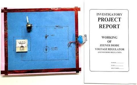
Zener Diode Voltage Regulator and Regulation Physics Working Model Educational Investigatory Project
Code B0C3H7B6HJ
- Paid for and delivered by Amazon. The current price and the delivery date for your PIN code are shown there.
- Sold by Gurukul Technicals Institute, Delhi.
- Need a different topic, a custom version or a school order? Ask on WhatsApp.
In this project guide
Ready-made model
About this model
This physics working model shows a Zener diode used as a voltage regulator, which keeps the output voltage steady even when the input changes. It demonstrates reverse breakdown, the property that makes the Zener diode useful in power supplies.
How it works
The science behind it
The idea the model demonstrates, in words you can use in your report and when you explain it.
A Zener diode is a heavily doped p-n junction diode designed to work in reverse bias. As the reverse voltage rises, very little current flows until it reaches the breakdown voltage, Vz; beyond that, the current can change a lot while the voltage stays almost fixed at Vz. In a regulator, the Zener is connected in reverse across the load, with a series resistor Rs between the supply and the diode. If the input rises, the extra voltage drops across Rs and the Zener draws more current, so the load voltage stays close to Vz. The series resistor sets the current: Rs = (Vin − Vz)/I. For a 9 V supply, a 5.1 V Zener and about 20 mA, Rs = 3.9 V ÷ 0.02 A = 195 Ω, so the standard 220 Ω value, giving about 18 mA, is used. Low-voltage Zeners break down mainly by the Zener effect and higher-voltage ones mainly by avalanche breakdown.
Make it yourself
Make a Zener diode voltage regulator yourself
Build your own version from scratch, or use the steps to understand how the ready-made model is put together before you present it.
What you need 8
Step by step 8 steps
Find the cathode of the Zener diode: it is the end with the band.
Connect the series resistor from the positive of the cells to the Zener's cathode, and the Zener's anode to the negative, so that the diode is reverse biased.
Connect the 2.2 kΩ load resistor across the Zener. The voltage across it is the regulated output.
Connect one multimeter across the cells (input) and the other across the load (output), both on DC volts.
Start with two cells (3 V) and record the input and output. Add one cell at a time up to eight cells (12 V), recording both voltages each time.
Now keep the input at 9 V and change the load from 10 kΩ to 4.7 kΩ to 2.2 kΩ, noting the output each time.
Plot output voltage against input voltage. The line should rise at first and then flatten close to 5.1 V.
Connect the LED indicator across the output and show visitors that its brightness hardly changes as cells are added.
Read this first
Safety first
Go through these points before you build or switch anything on. Younger students should do this with an adult.
- Never connect the Zener to the cells without the series resistor; it would draw a large current and overheat.
- Keep to 12 V or less from cells, and never short the cell pack, as the wires and cells get hot quickly.
- The series resistor can get warm at 12 V, so hold the board rather than the resistor.
- Do not mix old and new cells in the pack.
Troubleshooting
If something does not work
The usual problems with this model and how to fix them. Open a problem to see the fix.
The output stays at about 0.7 V whatever the input
The Zener is the wrong way round and is forward biased. Turn it so the banded end faces the series resistor.
The output simply follows the input and never levels off
The Zener is not connected, is damaged, or has a higher voltage rating than you think. Read the number printed on it and check its connections.
The output drops when a smaller load resistor is connected
The load is taking more current than the series resistor can supply. Use a larger load resistance or a smaller series resistor, keeping the Zener within its power rating.
The output is well below 5.1 V at the lowest input
That is expected at 3 V and 4.5 V: below about 6 V the Zener is not yet conducting, so the output simply follows the input. This is the rising part of your graph; regulation starts once the input is comfortably above 5.1 V.
Exhibition day
How to present it
A running order for the exhibition table or the practical, step by step.
If the input voltage can be varied, show on a multimeter that the output stays nearly the same.
Draw the circuit and point out that the Zener is connected in reverse bias.
Sketch the Zener's reverse V-I curve and mark the breakdown point.
Explain the job of the series resistor, as it is the most common viva question on this project.
Practice
Viva questions
Practice questions on this model, with short answers. Try each one aloud before you open the answer.
Why is a Zener diode connected in reverse bias in a regulator?
Because its useful property, a nearly constant voltage at breakdown, appears only in reverse bias.
What is the function of the series resistor?
It limits the current through the Zener diode and takes up the difference between the input voltage and the Zener voltage.
How is a Zener diode different from an ordinary diode?
It is heavily doped so that it breaks down at a sharp, known reverse voltage, and it can work there without damage as long as the current is limited.
What happens to the load voltage if the input voltage rises slightly?
It stays almost constant, because the Zener draws extra current and the extra voltage drops across the series resistor.
Project file
Project file outline
The headings of the project file, in order. Give each heading its own section and write it in your own words.
Free ebook: Writing a Science Project FileContents
- Aim: to show that a Zener diode keeps the output voltage nearly constant when the input voltage or the load changes
- Apparatus
- Theory: reverse breakdown and the role of the series resistor
- Circuit diagram
- Procedure for line regulation and for load regulation
- Observation tables
- Graph of output voltage against input voltage
- Result
- Precautions and sources of error
Buying checklist
Before you buy
What to check before you order the model.
1Check these first
- Zener diodes are studied in senior secondary semiconductor electronics, but syllabuses differ, so check that your teacher accepts this topic.
- Check in the listing what input supply the model needs and whether batteries are included, and buy fresh cells before the exhibition.
- Look for the Zener's voltage printed on the diode or given in the listing, because you will need it in your calculations.
- Test it with a multimeter a few days before submission, so you can show real readings and not only a glowing LED.
- Keep the box to protect the board and components in your school bag.
- Check the delivery date for your PIN code on the marketplace, and order well before the exhibition or practical.
- Practise explaining it. Judges ask what the model shows and why; knowing the science matters as much as the model. The viva questions above are a good place to start.
Next steps
Take it further
Ways to turn this model into a bigger investigation or a stronger exhibition entry.
Plot the full reverse characteristic of the Zener using a potentiometer as a variable supply, and mark the breakdown knee.
Calculate the percentage line regulation and load regulation from your readings.
Compare two Zeners of different voltages, or compare the Zener circuit with a three-pin regulator IC.
Audience
Who it suits
Suits Class 12 physics investigatory projects on semiconductor devices and diploma or ITI electronics learners.
- ClassClass 10 to 12
- SubjectPhysics
- TypeReady-made model
Free to read
Free ebooks for this topic
Free PDF ebooks from Gurukul Technicals Institute on the science, the making and the presenting of projects like this one.
- Free PDF ebook
Electricity and Magnetism Experiments
Hands-on experiments with cells, wires, bulbs and magnets
- Free PDF ebook
Physics Working Models Explained
Twenty classic models, how each works and how to make it
- Free PDF ebook
Investigatory Projects for Class 11 and 12
Topics, method and report structure for physics, chemistry and biology
- Free PDF ebook
Your Science Exhibition Guide
Choose a project, build it, present it and answer the judges with confidence