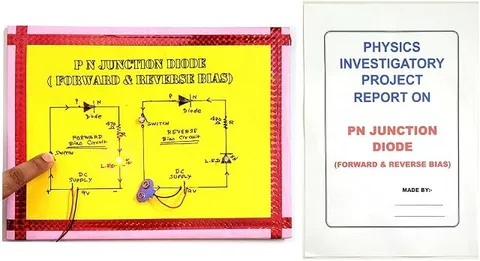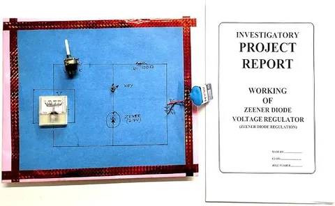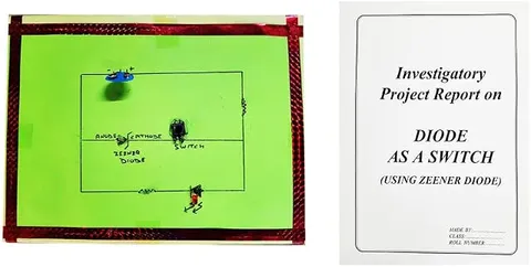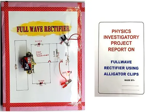
- Physics
- DIY kit
- Class 10 to 12
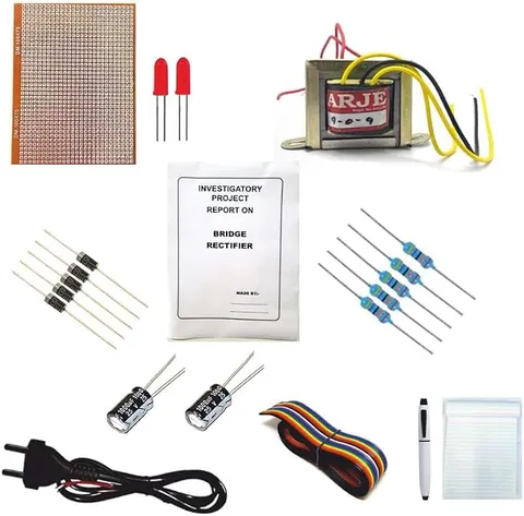
Bridge Rectifier Diode Project Kit DIY Physics Investigatory Project Electronic Components
Code B0FGV2Y8SK
- Paid for and delivered by Amazon. The current price and the delivery date for your PIN code are shown there.
- Sold by Gurukul Technicals Institute, Delhi.
- Need a different topic, a custom version or a school order? Ask on WhatsApp.
In this project guide
DIY kit
About this kit
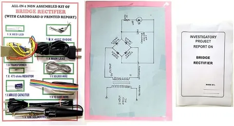
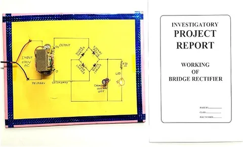
A do-it-yourself kit for building a bridge rectifier, the four-diode circuit that converts alternating current into direct current. Assembling it yourself makes a strong investigatory project, because you learn the job of every diode as you place it.
How it works
The science behind it
The idea the kit demonstrates, in words you can use in your report and when you explain it.
A diode lets current flow easily in only one direction, when it is forward biased. A bridge rectifier arranges four diodes in a diamond so that the output always has the same polarity. During the positive half cycle of the AC input, one pair of diagonally opposite diodes conducts; during the negative half cycle, the other pair conducts. In both halves the current passes through the load in the same direction, so the whole wave is used and the output is pulsating DC. Because two diodes conduct at any moment, the peak output is lower than the input peak by about two diode drops, roughly 1.4 V for silicon diodes. With 50 Hz input, the output pulses at 100 Hz. A capacitor placed across the output smooths these pulses into steadier DC. The charger of a mobile phone has a rectifier stage like this that turns household AC into DC before regulating it.
Make it yourself
Make a bridge rectifier with an indicator LED in each arm yourself
Everything you need and the order to do it in. Tick off the materials as you collect them.
What you need 9
Step by step 8 steps
Test every diode with the multimeter's diode range before soldering: about 0.5 to 0.7 V with the red probe on the plain end and the black probe on the banded end, and no reading the other way.
Make each arm from one diode in series with one LED, both facing the same way, so current enters the LED's long leg and leaves by the diode's banded end.
Join the four arms in a diamond: the two arms whose banded ends meet form the positive output, the two whose LED long legs meet form the negative output, and the two side corners are the AC inputs.
Give the two arms that conduct together the same colour: the arm from input A to the positive output and the arm from the negative output to input B are red, and the other two are green.
Connect the output LED and its 220 Ω resistor across the output, with the long leg towards the positive corner.
- Slow-motion test
Connect the 9 V battery through the reversing DPDT switch to the two inputs. In one position the red pair and the output LED light; flip it, and the green pair lights while the output LED stays lit.
Ask an adult to connect the AC adapter to the inputs instead. Now all four arm LEDs glow, because the two pairs take turns 50 times a second, too fast to see, and the output LED glows steadily.
Measure the AC input on the AC range and the DC output on the DC range, and note how much is lost in the two diodes and two LEDs that conduct in each half cycle.
Read this first
Safety first
Go through these points before you build or switch anything on. Younger students should do this with an adult.
- Use only a low-voltage AC adapter, connected by an adult; students must never wire anything to the mains or open the adapter.
- Use the soldering iron only with an adult, rest it in its stand, and never touch the tip or fresh joints.
- Trim component legs with the cutters pointing down, away from your eyes, and collect the clippings.
- Disconnect the power before changing any part on the board.
Troubleshooting
If something does not work
The usual problems with this kit and how to fix them. Open a problem to see the fix.
No LED lights in the slow-motion test
An arm may have its diode and LED facing opposite ways, which blocks it completely. Check each arm: current must enter the LED's long leg and leave by the diode's band.
The output LED lights in one switch position only
One arm of the pair that stays dark is reversed or has a dry solder joint. Re-check that pair's diodes and LEDs and resolder them.
The LEDs are dim in the battery test
That is expected, because the two arm LEDs, two diodes and the output LED in the path use most of the 9 V. Use a fresh battery and a dim room for the demonstration.
The battery test works but nothing happens on the adapter
The adapter is probably DC, not AC. Check that its label says AC output.
Exhibition day
How to present it
A running order for the exhibition table or the practical, step by step.
Before connecting, check each diode's direction from the band printed on its body, which marks the cathode.
Show on a chart, in two colours, which pair of diodes conducts in each half cycle.
Work only from a low-voltage AC source such as a step-down transformer, and never connect the circuit straight to the mains.
If you can borrow a CRO in the school lab, show the input and output waveforms side by side.
Practice
Viva questions
Practice questions on this kit, with short answers. Try each one aloud before you open the answer.
Why are four diodes used in a bridge rectifier?
Two diodes conduct in each half cycle, so with four diodes both halves of the AC are steered through the load in the same direction.
What is the output ripple frequency of a bridge rectifier for a 50 Hz input?
It is 100 Hz, because the output has one pulse for every half cycle of the input.
Why is the output peak slightly less than the input peak?
Two forward-biased diodes are in the path at any moment and each drops about 0.7 V for silicon, so about 1.4 V is lost.
What does the band on a diode indicate?
The band marks the cathode, the end towards which conventional current flows when the diode is forward biased.
Project file
Project file outline
The headings of the project file, in order. Give each heading its own section and write it in your own words.
Free ebook: Writing a Science Project FileContents
- Aim: to assemble a bridge rectifier and show which diodes conduct in each half cycle
- Introduction: AC, DC and the diode as a one-way valve
- Working of the bridge rectifier, with current paths for both half cycles
- Circuit diagram with an indicator LED in each arm
- Assembly and soldering steps
- Observations: slow-motion battery test and AC adapter test
- Readings of AC input and DC output, and the voltage lost in the arms
- Precautions and sources of error
- Conclusion and bibliography
Buying checklist
Before you buy
What to check before you order the kit, and what to do when it arrives.
1Before you order
- Check that rectifiers are part of your Class 12 syllabus and that your teacher accepts a self-assembled kit as an investigatory project.
- Read the listing to see which parts are named, and plan to arrange tools such as a soldering iron and a multimeter if you do not have them.
- Leave at least a week to assemble, test and write up the project before the submission date.
- Keep any spare parts in a labelled bag in case a joint needs redoing.
- Check the delivery date for your PIN code on the marketplace, and order well before the exhibition or practical.
- Check what is in the box on the marketplace listing, including any batteries or tools you need to add.
- Building it yourself: younger students should build with an adult, especially with motors, batteries and small parts.
2When it arrives
- Count and check the parts as soon as it arrives, and test each diode before you start soldering.
Next steps
Take it further
Ways to turn this kit into a bigger investigation or a stronger exhibition entry.
Add a 470 µF smoothing capacitor rated 25 V or more across the output and show how the DC reading changes.
Compare the bridge rectifier with a centre-tap rectifier on paper and list the advantages of each.
With a teacher, view the input and output on a school oscilloscope and photograph both waveforms.
Audience
Who it suits
Suits Class 12 physics investigatory projects and diploma or engineering students learning basic electronics.
- ClassClass 10 to 12
- SubjectPhysics
- TypeDIY kit
Free to read
Free ebooks for this topic
Free PDF ebooks from Gurukul Technicals Institute on the science, the making and the presenting of projects like this one.
- Free PDF ebook
Electricity and Magnetism Experiments
Hands-on experiments with cells, wires, bulbs and magnets
- Free PDF ebook
Physics Working Models Explained
Twenty classic models, how each works and how to make it
- Free PDF ebook
Investigatory Projects for Class 11 and 12
Topics, method and report structure for physics, chemistry and biology
- Free PDF ebook
Your Science Exhibition Guide
Choose a project, build it, present it and answer the judges with confidence