- Physics
- Ready-made model
- Class 10 to 12
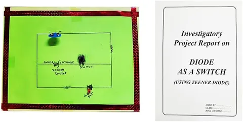
Using Zener as a Diode Circuit Physics Working Model Educational Investigatory Project
Code B0BN2DQ5FF
- Paid for and delivered by Amazon. The current price and the delivery date for your PIN code are shown there.
- Sold by Gurukul Technicals Institute, Delhi.
- Need a different topic, a custom version or a school order? Ask on WhatsApp.
In this project guide
Ready-made model
About this model
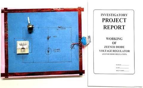
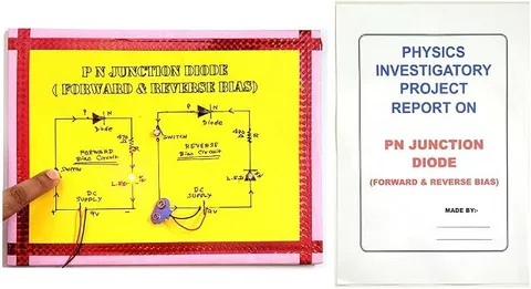
This physics investigatory model is about the Zener diode, a special PN junction diode that conducts like a normal diode in forward bias and holds a steady voltage in reverse breakdown. It helps a student compare a Zener with an ordinary diode and explain its use as a voltage regulator.
What the listing says
- Using Zeener as a Diode Circuit Physics Working Model Educational Investigatory Project
How it works
The science behind it
The idea the model demonstrates, in words you can use in your report and when you explain it.
A Zener diode is a heavily doped PN junction with a very thin depletion region. In forward bias it behaves like an ordinary silicon diode, conducting after about 0.7 V. In reverse bias, only a tiny current flows until the voltage reaches the Zener voltage, Vz. At that point breakdown occurs, and the current can rise a lot while the voltage across the diode stays almost constant. Unlike an ordinary diode, a Zener is designed to work safely in breakdown, provided a series resistor limits the current. This makes it a simple voltage regulator: connected in reverse bias across the load, it holds the output near Vz even when the input changes. The series resistor is found from R = (Vin − Vz) ÷ I. For a 9 V input, a 5.1 V Zener and 20 mA, R = 3.9 V ÷ 0.02 A = 195 Ω, so the next standard value, 220 Ω, is used.
Make it yourself
Make a Zener diode and ordinary diode comparison board yourself
Build your own version from scratch, or use the steps to understand how the ready-made model is put together before you present it.
What you need 11
Step by step 8 steps
Wire the potentiometer as a voltage divider: its two outer pins to battery positive and negative, and the middle pin as the adjustable output.
From the middle pin, run the 470 Ω resistor and the current meter (on the mA range) in series to the DPDT switch, which feeds whichever diode the two-way switch selects.
Connect the voltage meter straight across the diode terminals, so it reads the voltage on the diode alone.
- Forward bias
Set the DPDT so the diode's plain end (anode) faces positive, raise the voltage slowly and record voltage and current. For both diodes the current rises sharply near 0.7 V.
- Reverse bias
Flip the DPDT and repeat. The ordinary diode passes almost no current all the way up, while the Zener stays almost off until about 4.7 V and then lets the current climb while its voltage hardly changes.
Plot both diodes' V–I curves on one sheet, forward bias to the right and reverse bias to the left, and mark the Zener voltage.
- Regulator test
Keep the Zener in reverse bias, connect the LED and its resistor across it, and turn the input up from about 6 V to 9 V. Once the input is well above 4.7 V, the voltage across the Zener and LED stays almost steady.
Label the board with both circuit diagrams, the bias directions and your table of readings.
Read this first
Safety first
Go through these points before you build or switch anything on. Younger students should do this with an adult.
- Use only the 9 V battery; never feed the board from an opened adapter or anything wired to the mains.
- Always keep the 470 Ω resistor in series; a Zener or LED connected straight across the battery overheats.
- Use the soldering iron only with an adult, rest it in its stand, and do not touch the tip or fresh joints.
- Disconnect the battery while changing connections, and if any part gets hot, switch off and look for a short circuit.
Troubleshooting
If something does not work
The usual problems with this model and how to fix them. Open a problem to see the fix.
The Zener behaves just like the ordinary diode in reverse bias
The voltage reaching it may be below its rating, because the series resistor and the potentiometer drop part of the 9 V. Turn the potentiometer fully up, use a fresh battery, or use a lower-voltage Zener such as 3.3 V.
Both diodes conduct at about 0.7 V in both switch positions
The DPDT is not reversing the diode, usually because its cross wires are not crossed. Check with the multimeter's diode range that the diode's direction really changes when you flip the switch.
The current meter always reads zero
On many meters the lead must go in a separate mA socket, and the fuse may have blown. Check the socket, or measure the voltage across the 470 Ω resistor and work out the current as I = V ÷ R.
The regulated voltage drops when the LED is connected
The input is too low to keep the Zener in breakdown while also feeding the load. Raise the input, or use a lighter load.
Exhibition day
How to present it
A running order for the exhibition table or the practical, step by step.
Show the diode in forward bias first, then in reverse bias, and explain what changes at the Zener voltage.
Plot the V-I characteristic and mark the breakdown region where the voltage stays nearly constant.
If you can vary the input voltage, show that the output across the Zener barely changes.
Point to the series resistor and explain that without it the Zener could overheat.
Practice
Viva questions
Practice questions on this model, with short answers. Try each one aloud before you open the answer.
What makes a Zener diode different from an ordinary PN junction diode?
It is heavily doped and designed to work safely in reverse breakdown, where it keeps the voltage across it almost constant.
In which bias is a Zener diode used as a voltage regulator?
In reverse bias, connected across the load with a resistor in series.
Why is a resistor connected in series with a Zener diode?
It limits the current so the Zener does not overheat, and it takes up the difference between the input voltage and the Zener voltage.
How does a Zener diode behave in forward bias?
Like an ordinary silicon diode: it starts conducting after about 0.7 V.
Project file
Project file outline
The headings of the project file, in order. Give each heading its own section and write it in your own words.
Free ebook: Writing a Science Project FileContents
- Aim: to compare the V–I characteristics of a Zener diode and an ordinary diode, and to use the Zener as a voltage regulator
- Introduction: PN junction diodes in forward and reverse bias
- Zener breakdown and why heavy doping gives a sharp breakdown voltage
- Circuit diagram of the comparison board
- Observation tables: forward and reverse readings for both diodes
- V–I graph and finding the Zener voltage
- The Zener as a voltage regulator: readings with changing input
- Precautions and sources of error
- Conclusion and bibliography
Buying checklist
Before you buy
What to check before you order the model, and what to do when it arrives.
1Before you order
- Check that semiconductor devices and the Zener diode are in your syllabus (Class 12 physics) and whether your teacher wants V–I readings.
- Read the listing to see what the model is described as doing, and note any battery or meter you need to arrange.
- Practise explaining why a Zener is safe in breakdown while an ordinary diode would be damaged at its own breakdown voltage.
- Keep the box and carry the model flat so no component legs are bent.
- Check the delivery date for your PIN code on the marketplace, and order well before the exhibition or practical.
2When it arrives
- When it arrives, test it with a multimeter and take a full set of readings for your file a few days before submission.
Next steps
Take it further
Ways to turn this model into a bigger investigation or a stronger exhibition entry.
Test Zeners of two or three different ratings and compare how sharp each breakdown is on your graph.
Find the lowest input voltage at which regulation still holds for different load resistances and present it as a graph.
Compare the Zener regulator with a three-pin regulator chip of the 7805 type and list the advantages of each.
Audience
Who it suits
Suits Class 12 physics investigatory projects on semiconductor devices and diploma or first-year engineering electronics labs.
- ClassClass 10 to 12
- SubjectPhysics
- TypeReady-made model
Free to read
Free ebooks for this topic
Free PDF ebooks from Gurukul Technicals Institute on the science, the making and the presenting of projects like this one.
- Free PDF ebook
Electricity and Magnetism Experiments
Hands-on experiments with cells, wires, bulbs and magnets
- Free PDF ebook
Physics Working Models Explained
Twenty classic models, how each works and how to make it
- Free PDF ebook
Investigatory Projects for Class 11 and 12
Topics, method and report structure for physics, chemistry and biology
- Free PDF ebook
Your Science Exhibition Guide
Choose a project, build it, present it and answer the judges with confidence