- Physics
- DIY kit
- Class 10 to 12
- Printed report included
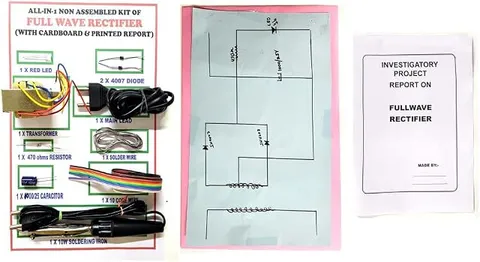
Full Wave Bridge Rectifier Kit DIY for 12th Class with Board and Report Physics Educational Investigatory Project for School & Colleges
Code B0DK22BYLR
- Paid for and delivered by Amazon. The current price and the delivery date for your PIN code are shown there.
- Sold by Gurukul Technicals Institute, Delhi.
- Need a different topic, a custom version or a school order? Ask on WhatsApp.
In this project guide
DIY kit
About this kit
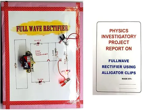
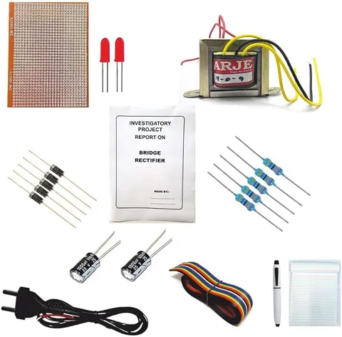
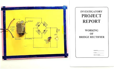
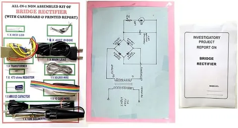
This DIY kit is for building a full wave bridge rectifier, the four-diode circuit that turns AC into DC in nearly every adaptor and charger. The listing says it includes a board and a report for a Class 12 investigatory project. Building it yourself makes it much easier to explain in the viva which diodes conduct and why.
How it works
The science behind it
The idea the kit demonstrates, in words you can use in your report and when you explain it.
A full wave bridge rectifier uses four diodes, D1 to D4, arranged so that two opposite diodes conduct together. During the positive half cycle one pair, say D1 and D3, is forward biased and current flows through the load from top to bottom. During the negative half cycle D1 and D3 are reverse biased and the other pair, D2 and D4, conducts, yet the current through the load still flows from top to bottom. So both halves of the AC wave are used. For ideal diodes the average output is Vdc = 2Vm/π, about 0.637 Vm, twice that of a half wave rectifier, and the ripple factor falls to about 0.48. Each diode faces a peak inverse voltage of only Vm, and no centre-tap transformer is needed. These advantages explain why a bridge, often sold as a single four-pin package, sits at the input of almost every mobile charger and laptop adaptor.
Make it yourself
Make a full wave bridge rectifier yourself
Everything you need and the order to do it in. Tick off the materials as you collect them.
What you need 7
Step by step 8 steps
Test each diode on the multimeter's diode range: it should read roughly 0.5 to 0.7 V one way and show no reading the other way.
Solder the four diodes as a bridge: two striped ends meet at the positive output, two plain ends at the negative output, and the other two corners are the AC inputs.
Connect the load resistor, and the output LED with its resistor, across the output, with the LED's long leg to positive.
For the slow-motion test, connect the 9 V battery to the two input corners through the reversing switch, so you can play each half cycle by hand.
With the switch one way, measure the voltage across each diode: two show about 0.7 V (conducting) and two show a larger voltage (blocking). Note the output polarity.
- Flip the switch
The other pair now conducts, yet the output LED stays lit and the output polarity does not change.
Disconnect the battery. With an adult, connect the AC adapter to the input corners and plug it in, then measure the DC output.
Unplug, add the capacitor across the output (stripe to negative), power it again and measure to see the smoothing.
Read this first
Safety first
Go through these points before you build or switch anything on. Younger students should do this with an adult.
- Only a ready-made low-voltage AC adapter is used for the AC test, plugged in by an adult; students never wire anything to mains.
- Never connect the battery and the AC adapter to the board at the same time.
- Fit the capacitor the right way round, and unplug before changing anything.
- Solder the bridge only with an adult, and let the board cool before testing it.
Troubleshooting
If something does not work
The usual problems with this kit and how to fix them. Open a problem to see the fix.
The output LED lights in one switch position only
A diode in the second pair is open or reversed. Check the two diodes that should conduct in that position.
A diode or the battery gets hot
A diode is reversed and is shorting the input. Disconnect at once and check all four directions.
The DC output is lower than I expected
In a bridge, current passes through two diodes in series, so about 1.4 V is lost, and the meter shows an average value. Note this in your file.
The meter shows a negative reading
The probes are swapped or the output terminals are mislabelled. The red probe goes to the corner where the striped ends meet.
Exhibition day
How to present it
A running order for the exhibition table or the practical, step by step.
Trace the current path for both half cycles with arrows of two colours on your circuit diagram.
Show that the output polarity stays the same even though the input keeps reversing.
If you add a filter capacitor, compare the output with and without it on a multimeter or CRO.
Identify the band on each diode and show how the four diodes are oriented in the bridge.
Practice
Viva questions
Practice questions on this kit, with short answers. Try each one aloud before you open the answer.
How many diodes are used in a bridge rectifier, and how many conduct at a time?
Four diodes are used, and two of them conduct in each half cycle.
What is the average output voltage of a full wave rectifier?
Vdc = 2Vm/π, about 0.637 times the peak voltage, for ideal diodes.
Why does a bridge rectifier not need a centre-tap transformer?
Because the four diodes reverse the load connection on alternate half cycles, giving full wave output from an ordinary two-terminal secondary.
What is the ripple factor of a full wave rectifier?
About 0.48, much lower than the 1.21 of a half wave rectifier.
Project file
Project file outline
The headings of the project file, in order. Give each heading its own section and write it in your own words.
The listing includes a printed project report: use this outline to check that your own file covers every part.
Free ebook: Writing a Science Project FileContents
- Aim: to build a full wave bridge rectifier and show that it uses both halves of the AC cycle
- Construction of the bridge and the job of each diode
- Slow-motion battery test: which pair conducts in each half cycle
- Input and output waveforms of the bridge
- Observation table: diode voltages for each switch position, and DC output with and without the capacitor
- Average output and ripple compared with a half wave rectifier
- Bridge rectifiers in phone chargers and adaptors
- Precautions, errors from the diode voltage drops, and conclusion
Buying checklist
Before you buy
What to check before you order the kit, and what to do when it arrives.
1Before you order
- The listing says a board and a report are included; check that the report's circuit diagram matches your board.
- See whether an AC supply is needed, and arrange for an adult to provide a low-voltage AC adapter.
- Build and test it at least a few days before your practical exam or viva.
- Keep the box to carry the finished board safely.
- Check the delivery date for your PIN code on the marketplace, and order well before the exhibition or practical.
- The project report is a learning aid. Read it, understand how the model works, and write your own observations; schools expect your own work.
2When it arrives
- On arrival, check the diodes and their stripes before you start soldering.
Next steps
Take it further
Ways to turn this kit into a bigger investigation or a stronger exhibition entry.
Show the input and output on an oscilloscope in the school lab.
Add a 5 V regulator after the capacitor to turn it into a simple regulated supply.
Compare your four-diode bridge with a ready-made single-package bridge rectifier.
Audience
Who it suits
Class 12 physics investigatory projects on rectifiers and semiconductor diodes, and ITI or diploma electronics labs.
- ClassClass 10 to 12
- SubjectPhysics
- TypeDIY kit
- Project reportPrinted report included
Free to read
Free ebooks for this topic
Free PDF ebooks from Gurukul Technicals Institute on the science, the making and the presenting of projects like this one.
- Free PDF ebook
Electricity and Magnetism Experiments
Hands-on experiments with cells, wires, bulbs and magnets
- Free PDF ebook
Physics Working Models Explained
Twenty classic models, how each works and how to make it
- Free PDF ebook
Investigatory Projects for Class 11 and 12
Topics, method and report structure for physics, chemistry and biology
- Free PDF ebook
Your Science Exhibition Guide
Choose a project, build it, present it and answer the judges with confidence