- Physics
- Ready-made model
- Class 10 to 12
Bridge Rectifier Physics Working Model Educational Investigatory Project-15 Months And Up, Multicolor For Baby
Code B0C3H5TQ46
- Paid for and delivered by Amazon. The current price and the delivery date for your PIN code are shown there.
- Sold by Gurukul Technicals Institute, Delhi.
- Need a different topic, a custom version or a school order? Ask on WhatsApp.
In this project guide
Ready-made model
About this model
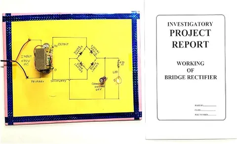
A physics working model of a bridge rectifier, the arrangement of four diodes that turns alternating current into direct current. It suits Class 12 students who want to show the AC to DC conversion that happens inside every charger and adaptor.
How it works
The science behind it
The idea the model demonstrates, in words you can use in your report and when you explain it.
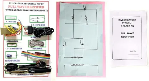
A p-n junction diode conducts when forward biased and blocks current when reverse biased, and this one-way behaviour makes rectification possible. In a bridge rectifier, four diodes form a closed loop. In the positive half cycle, two diodes are forward biased and carry current through the load; in the negative half cycle, the other two take over, and the current through the load still flows the same way. The result is full wave rectification without the centre-tapped transformer that a two-diode design needs. Each diode only has to withstand a peak inverse voltage equal to the peak input voltage, Vm, half of what each diode faces in a centre-tap rectifier. The output is still pulsating, so a filter capacitor is added: it charges near each peak and discharges slowly through the load between peaks. Inside a phone charger, India's 230 V, 50 Hz mains is rectified this way before being turned into a low, steady voltage.
Make it yourself
Make a bridge rectifier model yourself
Build your own version from scratch, or use the steps to understand how the ready-made model is put together before you present it.
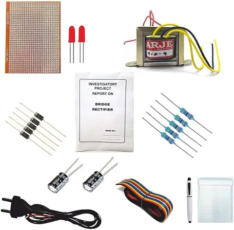
What you need 10
Step by step 9 steps
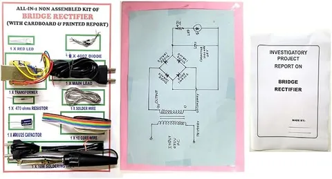
Arrange the four diodes in a diamond on the base. Two diodes have their banded (cathode) ends meeting at the + output, two have their plain (anode) ends meeting at the − output, and the two remaining corners are the AC inputs.
Connect the red LED and its 1 kΩ resistor across the output, long leg towards the + output.
Fix the capacitor across the output on a removable link, with its stripe (negative) towards the − output.
- Slow demonstration first
Wire the 9 V battery to the AC inputs through the DPDT switch as a reversing switch, so each flip swaps the polarity.
Flip the switch back and forth: the input indicator changes colour each time, but the output LED stays lit the same way. This is rectification, slowed down to human speed.
Disconnect the battery. With the adapter unplugged, connect its low-voltage AC output leads to the AC input terminals, then ask an adult to plug the adapter into the socket.
Measure the input on the AC volts range and the output on the DC volts range, first without and then with the capacitor connected.
With the capacitor, the DC reading is higher than the AC reading, because it charges to the peak voltage (about 1.41 times the AC reading) minus about 1.4 V lost in two diodes.
With the adapter unplugged, remove one diode and measure again: the output becomes half-wave and the average voltage drops.
Read this first
Safety first
Go through these points before you build or switch anything on. Younger students should do this with an adult.
- Use only a low-voltage AC adapter, plugged into the wall socket by an adult. Students must never open the adapter, touch mains wiring or connect any part of this circuit to the mains.
- Fit the electrolytic capacitor the right way round and use one rated well above the peak voltage, at least 25 V for a 9 V AC supply; a reversed or under-rated capacitor can bulge or burst.
- Unplug the adapter before changing any connection, and let the capacitor discharge through the LED first.
- Solder only with an adult present, and keep the iron in its stand.
Troubleshooting
If something does not work
The usual problems with this model and how to fix them. Open a problem to see the fix.
The output LED does not light
A diode or the LED may be the wrong way round, or the output terminals may be swapped. Check each diode's band against your diagram.
The adapter gets hot or the output reads zero
Two diodes may be reversed so that they short-circuit the adapter's output. Ask an adult to unplug it at once, then check every diode's direction before trying again.
The DC output reads higher than the AC input
This is correct when the capacitor is fitted: it charges to the peak of the AC wave, which is about 1.41 times the AC reading, less the diode drops.
The output is only about half what you expected
One diode is probably open (broken), so only half of each cycle gets through. Test each diode with the multimeter's diode range and replace the faulty one.
Exhibition day
How to present it
A running order for the exhibition table or the practical, step by step.
Show the current path in each half cycle with arrows of two colours on a chart.
Explain why the output stays in one direction even though the input keeps reversing, pointing to each diode in turn.
Compare the bridge design with the centre-tap design: number of diodes, type of transformer and peak inverse voltage.
Do not connect the model to household mains yourself; ask your teacher which supply it should use.
Practice
Viva questions
Practice questions on this model, with short answers. Try each one aloud before you open the answer.
What is the main advantage of a bridge rectifier over a centre-tap rectifier?
It gives full wave rectification without a centre-tapped transformer, and each diode faces only half the peak inverse voltage.
What is peak inverse voltage?
It is the maximum reverse voltage that appears across a diode while it is not conducting, and the diode must be rated to withstand it.
How many diodes conduct at a time in a bridge rectifier?
Two diodes conduct at a time, one pair in each half cycle.
What is the role of the filter capacitor?
It stores charge near each peak and releases it between peaks, reducing the ripple in the output.
Project file
Project file outline
The headings of the project file, in order. Give each heading its own section and write it in your own words.
Free ebook: Writing a Science Project FileContents
- Aim: to convert low-voltage AC into DC using a full-wave bridge rectifier
- Theory: the p-n junction diode in forward and reverse bias
- Working of the bridge in the positive and the negative half cycles
- Circuit diagram with diodes D1 to D4, the load and the filter capacitor
- Slow demonstration with a battery and a reversing switch
- Observations: AC input voltage, and DC output with and without the capacitor
- Comparison of half-wave, centre-tap full-wave and bridge rectifiers
- Uses: phone chargers, adaptors and DC power supplies
- Conclusion and bibliography
Buying checklist
Before you buy
What to check before you order the model.
1Check these first
- Check that rectifiers are in your syllabus (semiconductor devices) and whether your teacher wants readings as well as a model.
- Ignore the age wording in the listing title: this is an electronics model for senior classes, with small parts, not a toy for young children.
- Read the listing to see what power source the model is meant to use, and plan for a low-voltage AC adapter connected by an adult.
- Test it a few days before the exhibition with the supply you will use on the day.
- Keep the box and carry the model so the diodes and wires are not bent.
- Check the delivery date for your PIN code on the marketplace, and order well before the exhibition or practical.
- Practise explaining it. Judges ask what the model shows and why; knowing the science matters as much as the model. The viva questions above are a good place to start.
Next steps
Take it further
Ways to turn this model into a bigger investigation or a stronger exhibition entry.
Add a 7805 regulator or a zener diode after the capacitor to make a steady 5 V supply, and measure how steady it is.
Measure the ripple with different capacitor values and loads, and compare with the estimate Vr ≈ I/(2fC), where f is the 50 Hz supply frequency.
If your school laboratory has an oscilloscope, ask your teacher to help you view the waveforms before rectification, after it and after smoothing.
Audience
Who it suits
Suits Class 12 physics exhibitions and practicals on semiconductor devices; it is a study model for older students, not a toy for young children.
- ClassClass 10 to 12
- SubjectPhysics
- TypeReady-made model
Free to read
Free ebooks for this topic
Free PDF ebooks from Gurukul Technicals Institute on the science, the making and the presenting of projects like this one.
- Free PDF ebook
Electricity and Magnetism Experiments
Hands-on experiments with cells, wires, bulbs and magnets
- Free PDF ebook
Physics Working Models Explained
Twenty classic models, how each works and how to make it
- Free PDF ebook
Investigatory Projects for Class 11 and 12
Topics, method and report structure for physics, chemistry and biology
- Free PDF ebook
Your Science Exhibition Guide
Choose a project, build it, present it and answer the judges with confidence