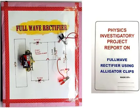
- Physics
- Ready-made model
- Class 10 to 12
Full Wave Rectifier
Code B0G2THG81S
- Paid for and delivered by Amazon. The current price and the delivery date for your PIN code are shown there.
- Sold by Gurukul Technicals Institute, Delhi.
- Need a different topic, a custom version or a school order? Ask on WhatsApp.
In this project guide
Ready-made model
About this model
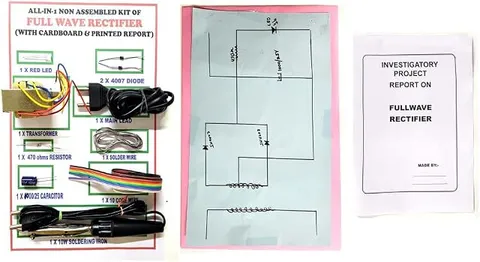
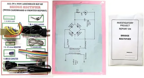
This Class 12 physics project, as its title says, is about the full wave rectifier, the circuit that converts alternating current (AC) into direct current (DC) using diodes. It helps a student explain how both halves of the AC cycle are used and how the output can be smoothed.
What the listing says
- AC to DC Conversion Physics Project for Class 12
How it works
The science behind it
The idea the model demonstrates, in words you can use in your report and when you explain it.
Alternating current changes direction many times a second; Indian mains supply is 230 V at 50 Hz. A diode lets current pass in one direction only, so it can be used for rectification. A half wave rectifier uses one diode and passes only the positive half cycles, wasting the rest. A full wave rectifier uses both halves. In the centre-tap type, two diodes conduct on alternate half cycles; in the bridge type, four diodes do the same job without a centre-tapped transformer. In both, current flows through the load in the same direction during each half cycle, giving pulsating DC with a ripple frequency of 100 Hz for a 50 Hz input. A capacitor across the load smooths the ripple by charging near each peak and discharging between peaks. The maximum efficiency of a full wave rectifier is 81.2%, double the 40.6% of a half wave rectifier. Every mobile charger has a rectifier stage to turn mains AC into DC.
Make it yourself
Make a full wave rectifier with a capacitor filter yourself
Build your own version from scratch, or use the steps to understand how the ready-made model is put together before you present it.
What you need 10
Step by step 8 steps
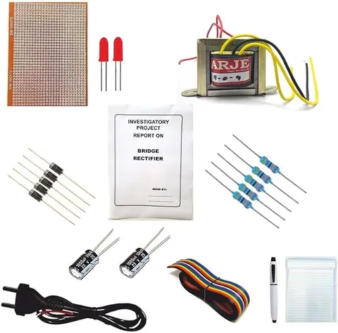
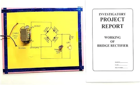
Solder the four diodes into a bridge: the two diodes whose bands meet form the positive output, the two whose plain ends meet form the negative output, and the two remaining corners are the AC inputs.
Before any AC is connected, test each diode with the multimeter's diode range: about 0.5 to 0.7 V one way and no reading the other way.
Connect the 1 kΩ load and the LED across the DC output, and fit the three capacitors, each through its own switch, across the same output with the longer (positive) leg to the positive side.
With all capacitors switched out, ask an adult to plug in the adapter. Measure the AC input on the AC range and the DC output on the DC range, and write both down.
Switch in the 100 µF capacitor and measure again, then the 470 µF, then the 1000 µF. The DC reading rises towards the peak value, about 1.4 times the AC reading minus about 1.4 V for the two conducting diodes.
Change the load to 470 Ω and repeat: a heavier load drains the capacitor more between peaks, so the output falls further with the smaller capacitors.
Plot DC output against capacitance for each load, and explain the shape of the graphs in terms of ripple.
After the readings, ask an adult to unplug the adapter, then wait a minute for the capacitors to discharge through the load before touching the board.
Read this first
Safety first
Go through these points before you build or switch anything on. Younger students should do this with an adult.
- Use only a low-voltage AC adapter, plugged in and switched on by an adult; students must never wire anything to the mains or open the adapter.
- Fit every electrolytic capacitor with its positive leg to the positive output and use ones rated 25 V or more; a reversed or under-rated capacitor can burst.
- Use the soldering iron only with an adult, rest it in its stand, and let the board cool before handling it.
- Unplug the adapter and let the capacitors discharge before changing any connection.
Troubleshooting
If something does not work
The usual problems with this model and how to fix them. Open a problem to see the fix.
The output looks just like the input and nothing changes with the capacitors
Your adapter probably gives DC, not AC; most phone and router adapters do. Check that its label says AC output, often shown with a wavy line.
The DC output reads zero
A diode may be reversed, or the output is being taken from the wrong corners. Check the bridge against the diagram and test each diode again.
The output with a capacitor is lower than expected
The capacitor may be reversed or too small for the load, or the adapter's voltage drops under load. Check the polarity, and measure the adapter's AC output while the load is connected.
A diode or the adapter gets warm
The load resistance is too low or the output is shorted. Unplug it, look for solder bridges, and use the 1 kΩ load.
Exhibition day
How to present it
A running order for the exhibition table or the practical, step by step.
Draw the input and output waveforms side by side, showing how the negative halves are flipped to the same side.
If your school lab has a CRO, show the output before and after adding the filter capacitor.
Explain which diodes conduct in each half cycle, using arrows on the circuit diagram.
Compare half wave and full wave rectifiers in a small table of diodes used, ripple frequency and efficiency.
Practice
Viva questions
Practice questions on this model, with short answers. Try each one aloud before you open the answer.
What is the ripple frequency of a full wave rectifier with a 50 Hz input?
It is 100 Hz, twice the input frequency, because both half cycles appear at the output.
Why is a capacitor connected across the load?
It charges near each peak and discharges slowly between peaks, which smooths out the ripples in the output.
How does the maximum efficiency of a full wave rectifier compare with that of a half wave rectifier?
It is about 81.2%, twice the 40.6% maximum efficiency of a half wave rectifier.
How does a bridge rectifier differ from a centre-tap rectifier?
A bridge rectifier uses four diodes and needs no centre-tapped transformer, while the centre-tap type uses two diodes and a centre-tapped transformer.
Project file
Project file outline
The headings of the project file, in order. Give each heading its own section and write it in your own words.
Free ebook: Writing a Science Project FileContents
- Aim: to convert AC into DC with a full wave bridge rectifier and to study the effect of a capacitor filter
- Introduction: alternating and direct current, and the diode as a one-way valve
- Working of the bridge rectifier in each half cycle, with diagrams
- Pulsating DC, ripple and the job of the filter capacitor
- Circuit diagram and list of components
- Observation table: AC input and DC output for each capacitor and load
- Graph of DC output against capacitance
- Precautions and sources of error
- Conclusion and bibliography
Buying checklist
Before you buy
What to check before you order the model, and what to do when it arrives.
1Before you order
- Check that rectifiers are in your Class 12 syllabus and whether your teacher wants a centre-tap or a bridge circuit, since the listing just says full wave rectifier.
- Read the listing to find what power source the model needs, and arrange a low-voltage AC adapter if it uses one.
- Practise drawing the input and output waveforms, which examiners nearly always ask for.
- Keep the box and carry the board flat so the capacitors and diodes are not bent.
- Check the delivery date for your PIN code on the marketplace, and order well before the exhibition or practical.
2When it arrives
- Have an adult connect the power when it arrives, and take a full set of readings for your file well before the submission date.
Next steps
Take it further
Ways to turn this model into a bigger investigation or a stronger exhibition entry.
With a teacher, view the output on the school oscilloscope and photograph the waveform with no capacitor, with 100 µF and with 1000 µF.
Add a 7805 regulator after the filter and show that the output stays at 5 V even when the load changes.
Calculate the theoretical ripple factor of a full wave rectifier and compare it with that of a half wave rectifier.
Audience
Who it suits
Suits Class 12 physics investigatory projects on semiconductor devices, and diploma students starting on power supply circuits.
- ClassClass 10 to 12
- SubjectPhysics
- TypeReady-made model
Free to read
Free ebooks for this topic
Free PDF ebooks from Gurukul Technicals Institute on the science, the making and the presenting of projects like this one.
- Free PDF ebook
Electricity and Magnetism Experiments
Hands-on experiments with cells, wires, bulbs and magnets
- Free PDF ebook
Physics Working Models Explained
Twenty classic models, how each works and how to make it
- Free PDF ebook
Your Science Exhibition Guide
Choose a project, build it, present it and answer the judges with confidence
- Free PDF ebook
Writing a Science Project File
How to write the report, from the cover page to the bibliography