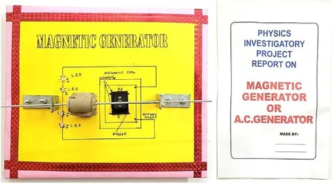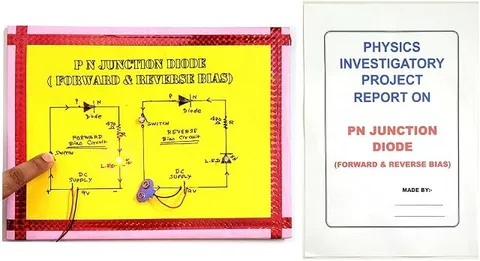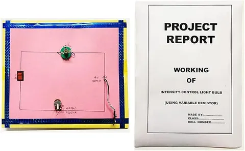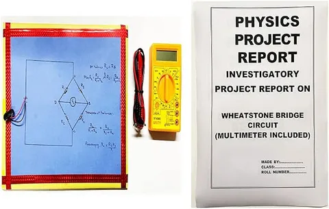
- Physics
- Ready-made model
- Class 10 to 12
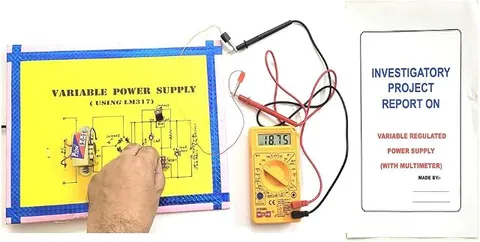
Ontex Electronics Variable Regulated Power Supply Using Multimeter Physics Investigatory Project Model Engineering College & Science Teaching Aid
Code B0DMKZM4JJ
- Paid for and delivered by Amazon. The current price and the delivery date for your PIN code are shown there.
- Sold by Gurukul Technicals Institute, Delhi.
- Need a different topic, a custom version or a school order? Ask on WhatsApp.
In this project guide
Ready-made model
About this model
This investigatory project model shows the stages by which a power supply turns alternating current (AC) into a steady direct current (DC) voltage that can be adjusted. The listing title says a multimeter is used to read the output, so a student can turn the control and watch the voltage change on the meter. It suits a Class 12 physics project on semiconductor devices or a first-year engineering lab demonstration.
How it works
The science behind it
The idea the model demonstrates, in words you can use in your report and when you explain it.
A regulated power supply works in four stages. First, a step-down transformer lowers the AC voltage according to its turns ratio, Vs/Vp = Ns/Np. Next, diodes rectify it: they let current flow in one direction only, so the output becomes pulsating DC. A filter capacitor then charges at each peak and releases charge between peaks, smoothing out most of the ripple. Finally, a regulator keeps the output steady even when the load or the input changes. In a variable supply a potentiometer sets the output; for example, with the common adjustable regulator LM317, Vout ≈ 1.25 V × (1 + R2/R1). A multimeter in DC voltage mode, connected in parallel across the output, confirms the value. The charger of a mobile phone is also a regulated DC supply: even when the mains voltage at home is a little high or low, it keeps giving a steady output of about 5 V.
Make it yourself
Make a variable regulated power supply yourself
Build your own version from scratch, or use the steps to understand how the ready-made model is put together before you present it.
What you need 8
Step by step 8 steps
Build the bridge rectifier on the perfboard with the four diodes, with the striped ends of two diodes meeting at the positive output.
Solder the 1000 µF capacitor across the bridge output, with its striped (negative) lead to the negative line.
Fit the regulator on its heat sink, check its pin order in its datasheet, and connect its input pin to the positive line.
Connect the 240 Ω resistor between the regulator's output and adjust pins, and the potentiometer from the adjust pin to the negative line.
Add the 10 µF capacitor across the output, then connect the output terminals and the multimeter.
Check every joint and the direction of each diode and capacitor against your circuit diagram before any power is applied.
With an adult, connect the AC adapter and plug it in; turn the knob and watch the meter rise from about 1.25 V to its highest value.
Connect the test bulb and check that the voltage stays nearly the same with the load added, which shows the regulator at work.
Read this first
Safety first
Go through these points before you build or switch anything on. Younger students should do this with an adult.
- Only a ready-made low-voltage AC adapter is used, connected and plugged in by an adult; students never wire the mains side or open a transformer.
- Electrolytic capacitors must go the right way round and be rated above the voltage they see; reversed or overloaded, they can swell or burst.
- The regulator and its heat sink get hot under load, so do not touch them while the supply is working.
- Unplug the adapter before changing any part, and give the large capacitor time to discharge.
- Solder only with an adult.
Troubleshooting
If something does not work
The usual problems with this model and how to fix them. Open a problem to see the fix.
The output stays at about 1.25 V whatever I do
The adjust pin is joined straight to the negative line, so the potentiometer is shorted out. Look for a solder bridge across it, and check that you used its middle pin and one outer pin.
The output is high and does not change
The potentiometer may be open, or wired by its two outer pins, which gives a fixed value; use its middle pin and one outer pin. Also check the 240 Ω resistor and the regulator's pin order in its datasheet.
The regulator gets very hot
The load draws too much current or the input is much higher than the output. Use a larger heat sink and a lighter load.
The meter shows zero
Check that the adapter gives AC output and is switched on, that the diodes face the right way and that the meter is on DC volts.
Exhibition day
How to present it
A running order for the exhibition table or the practical, step by step.
Draw the four blocks (transformer, rectifier, filter, regulator) on a chart and match each block to the part of the model that does that job as you explain it.
Turn the control slowly from minimum to maximum and let the judges read the multimeter themselves.
Prepare a small table of knob position against output voltage to prove the supply is truly variable.
Mention safety: keep hands away from any mains-side wiring and switch off before touching the circuit.
Practice
Viva questions
Practice questions on this model, with short answers. Try each one aloud before you open the answer.
Why do we need a regulator if the capacitor already smooths the output?
The capacitor reduces ripple, but the voltage still drops when the load current rises or the mains voltage changes. A regulator holds the output constant against both.
How should a multimeter be connected to measure the output voltage?
In DC voltage mode, in parallel across the output terminals, with the red probe on positive and the black probe on negative.
What is the job of the step-down transformer?
It lowers the mains AC voltage to a small, safer AC voltage according to the turns ratio of its windings. It works only on AC because it depends on a changing magnetic flux.
What is ripple?
Ripple is the small leftover AC variation riding on the DC output after rectification and filtering. A good regulated supply keeps it very small.
Project file
Project file outline
The headings of the project file, in order. Give each heading its own section and write it in your own words.
Free ebook: Writing a Science Project FileContents
- Aim: to build a power supply with an adjustable, steady DC output and measure it with a multimeter
- Block diagram: transformer, rectifier, filter and regulator
- How the bridge rectifier and the filter capacitor work
- The adjustable regulator and its output formula
- Observation table: knob position against output voltage
- Load test: output voltage with and without a load
- Uses of regulated supplies in laboratories and chargers
- Precautions with the hot regulator and the capacitors, sources of error and conclusion
Buying checklist
Before you buy
What to check before you order the model, and what to do when it arrives.
1Before you order
- Check in the listing what supply the model needs; any AC adapter must be supplied and connected by an adult.
- See whether the listing mentions a multimeter; if not, you will need one for your readings.
- Confirm the chapter (semiconductor devices) and class level with your teacher.
- Keep the box for transport, as knobs and terminals can snap off in a school bag.
- Check the delivery date for your PIN code on the marketplace, and order well before the exhibition or practical.
- Practise explaining it. Judges ask what the model shows and why; knowing the science matters as much as the model. The viva questions above are a good place to start.
2When it arrives
- Test it with an adult soon after it arrives, and record the lowest and highest output for your file.
Next steps
Take it further
Ways to turn this model into a bigger investigation or a stronger exhibition entry.
Compare the ripple with and without the 1000 µF capacitor, using an oscilloscope in the school lab or the multimeter's AC range as a rough guide.
Add a fixed 5 V regulator as a second output and compare fixed and adjustable regulators.
Measure the potentiometer's resistance at several settings, calculate the expected output with the formula and compare it with your readings.
Audience
Who it suits
Class 12 physics investigatory projects on semiconductor devices, and first-year engineering or diploma electronics labs.
- ClassClass 10 to 12
- SubjectPhysics
- TypeReady-made model
Free to read
Free ebooks for this topic
Free PDF ebooks from Gurukul Technicals Institute on the science, the making and the presenting of projects like this one.
- Free PDF ebook
Physics Working Models Explained
Twenty classic models, how each works and how to make it
- Free PDF ebook
Investigatory Projects for Class 11 and 12
Topics, method and report structure for physics, chemistry and biology
- Free PDF ebook
Your Science Exhibition Guide
Choose a project, build it, present it and answer the judges with confidence
- Free PDF ebook
Writing a Science Project File
How to write the report, from the cover page to the bibliography