Full Wave Rectifier
₹369MRP ₹1,000
 Gurukul Technicals InstituteComputer courses · Franchise centres · Projects & kitsBecome a Franchise PartnerMenu
Head office, Rana Pratap Bagh, Delhi
 40% off
Code B0HLY225MV
In this project guide
Ready-made model
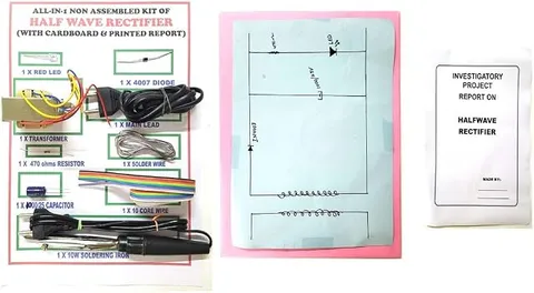
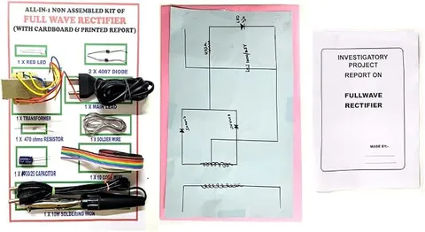
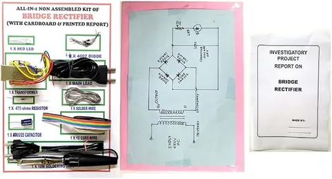
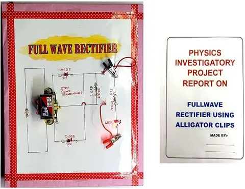
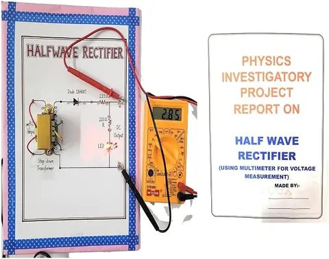
This Class 12 physics investigatory model shows a half wave rectifier and how to measure its output with a multimeter's probes. As shown in the photo, a chart titled Halfwave Rectifier has a real step-down transformer at the AC input, a 1N4007 diode, a 220 Ω series resistor, a 220 Ω load resistor R and a red LED at the DC output. A digital multimeter's probes are clipped to the output terminals. A printed report cover titled Half Wave Rectifier (Using Multimeter for Voltage Measurement) is also shown.
How it works
The idea the model demonstrates, in words you can use in your report and when you explain it.
A rectifier changes alternating current, which keeps reversing direction, into direct current, which flows one way. On this model a step-down transformer first lowers the AC voltage, and a single p-n junction diode, the 1N4007, does the rectifying. During the half cycle that makes the diode's anode positive, the diode is forward biased and conducts, so current flows through the resistors and the LED. During the other half cycle it is reverse biased and blocks the current. The output is a series of humps with gaps between them: pulsating DC that always flows the same way. On a 50 Hz supply, as Indian mains is, there are 50 humps a second, so the LED looks almost steady. For an ideal diode the average output is Vm/π, about 0.318 of the peak voltage Vm, and a real silicon diode also drops about 0.7 V while conducting. A multimeter on its DC range shows this average, which is why its reading is well below the AC reading at the transformer.
Make it yourself
Build your own version from scratch, or use the steps to understand how the ready-made model is put together before you present it.
Draw the circuit on the chart: the AC input on the left, the diode and series resistor along the top, the load resistor and LED down the right side, and the DC output test points marked + and -.
Fix screw terminals for the AC input and two brass test points for the DC output, where the multimeter probes can be clipped.
Connect the diode from one AC input terminal, with its band (cathode) towards the output, then the series 220 Ω resistor to the positive test point.
Connect the load resistor R and the LED in series between the positive and negative test points, with the LED's long leg towards the positive.
Join the other AC input terminal straight to the negative test point.
Check every joint, then let an adult connect the AC adapter's output to the input terminals and plug it in.
Set the multimeter to AC volts and measure across the input terminals. Then set it to DC volts, put the red probe on + and the black probe on -, and read the output.
Ask the adult to unplug the adapter, add the capacitor across the output with its stripe to the negative, then power it again and measure the higher DC reading.
Record all the readings in a table for your project file.
Read this first
Go through these points before you build or switch anything on. Younger students should do this with an adult.
Troubleshooting
The usual problems with this model and how to fix them. Open a problem to see the fix.
Check that the adapter's label says AC output and that it is switched on, then test the diode with the multimeter's diode range.
The probes are swapped or the diode is reversed. Put the red probe on + and check that the diode's band faces the output.
This is normal: the DC range shows the average of the humps, and the diode drops about 0.7 V. Explain it in your file.
The LED is the wrong way round. Its long leg must point towards the positive test point.
Clip the probes firmly on the test points instead of holding them, and check the multimeter's own battery.
Exhibition day
A running order for the exhibition table or the practical, step by step.
With an adult beside you, measure the AC voltage at the transformer's low-voltage output on the multimeter's AC range, keeping clear of its input side, then the DC output on its DC range, and explain why the DC reading is lower.
Point to the band on the 1N4007 and explain that it marks the cathode, the end towards which current flows when the diode conducts.
Draw the input sine wave and the output humps one above the other on a card beside the model.
Show the right way to use the probes: red on the positive terminal, black on the negative, and fingers behind the probe guards.
Practice
Practice questions on this model, with short answers. Try each one aloud before you open the answer.
Because only one half of each AC cycle reaches the load; the diode blocks the other half.
It lowers the AC voltage to a small, safe value for the diode and the LED, and keeps the circuit separate from the supply.
The DC range shows the average of the humps, only about 0.45 times the AC (rms) reading for half wave, and the diode also drops about 0.7 V.
50 Hz, because there is one output hump for every input cycle.
Project file
The headings of the project file, in order. Give each heading its own section and write it in your own words.
The listing photo shows a printed project report: if it comes with your order, use this outline to check that your own file covers every part.
Free ebook: Writing a Science Project FileContents
Buying checklist
What to check before you order the model, and what to do when it arrives.
Next steps
Ways to turn this model into a bigger investigation or a stronger exhibition entry.
With a teacher, view the input and output on a CRO in the school lab, and sketch both waveforms.
Try capacitors of different values and plot capacitance against the DC output reading.
Build a bridge rectifier on a second board and compare its output with the half wave readings.
Audience
Suits Class 12 physics investigatory projects on semiconductor diodes and rectifiers, and practical revision for ITI and diploma electronics students.
Free to read
Free PDF ebooks from Gurukul Technicals Institute on the science, the making and the presenting of projects like this one.
Hands-on experiments with cells, wires, bulbs and magnets
Twenty classic models, how each works and how to make it
Topics, method and report structure for physics, chemistry and biology
Choose a project, build it, present it and answer the judges with confidence