 55% off
- Physics
- DIY kit
- Class 10 to 12
- Printed report included
Half Wave Rectifier Kit DIY for 12th Class with Transformer, Board and Report, Physics Investigatory Project
Code B0DK22BH2B
- Paid for and delivered by Amazon or Flipkart. The current price and the delivery date for your PIN code are shown there.
- Sold by Gurukul Technicals Institute, Delhi.
- Need a different topic, a custom version or a school order? Ask on WhatsApp.
In this project guide
DIY kit
About this kit
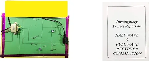
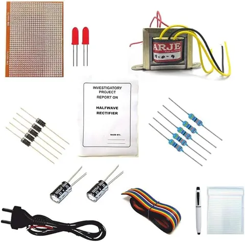
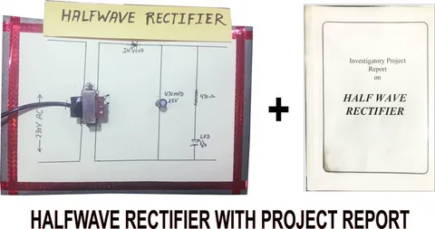
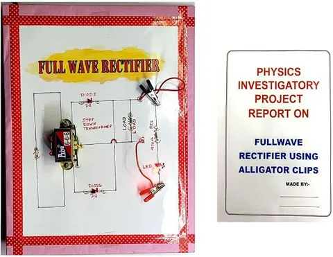
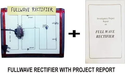
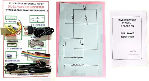
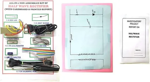
This DIY kit builds a half wave rectifier, the simplest circuit that turns AC into DC and a standard Class 12 physics topic. It has a step-down transformer with a mains lead, one 1N4007 diode, a 1000 µF 25 V smoothing capacitor, and a red LED with a 470 Ω resistor as the load, plus wire, solder, a soldering iron, the circuit drawn on cardboard and a printed report. With a single diode, the output is half wave.
How it works
The science behind it
The idea the kit demonstrates, in words you can use in your report and when you explain it.
Mains electricity in India is AC at 230 V and 50 Hz, so its direction reverses in every cycle. The step-down transformer lowers this to a low AC voltage by mutual induction, in the ratio of the turns on its two coils. A p-n junction diode such as the 1N4007 conducts only when forward biased. In the half cycle that makes its anode positive it conducts, dropping about 0.7 V, and current flows through the load. In the other half cycle it is reverse biased and blocks, so the output is a row of positive pulses with gaps: pulsating DC. The 1000 µF capacitor across the output charges to nearly the peak voltage in each pulse and then feeds the LED and its 470 Ω resistor through the gap, so the output is much smoother, with a small dip called ripple. Because only half of each cycle is used, the maximum efficiency of a half wave rectifier is about 40.6%, and its ripple is larger than a full wave rectifier's.
Make it yourself
Make a half wave rectifier with a filter capacitor yourself
Everything you need and the order to do it in. Tick off the materials as you collect them.
What you need 9
Step by step 10 steps
Lay the parts on the circuit drawn on the cardboard: the transformer at the bottom, the diode on one side, the capacitor across the output, and the 470 Ω resistor with the LED at the top.
Keep the mains lead unplugged for the whole build. If it is not already joined to the transformer's primary, an adult makes those two joints and covers each one fully with sleeving or tape.
Ask the adult to show you the transformer's low-voltage secondary wires; you solder only to two of them. If there are three, one is a centre tap, and using it with one outer wire halves the voltage. The peak, about 1.4 times the AC voltage, must stay below the capacitor's 25 V rating.
With an adult, heat the soldering iron on its stand, then solder one secondary wire to the plain end (anode) of the 1N4007.
Solder the diode's banded end (cathode) to the capacitor's positive lead, and the capacitor's striped negative lead to the other secondary wire.
Across the capacitor, solder the 470 Ω resistor in series with the LED, with the LED's longer leg towards the resistor on the diode's side.
Check every joint and polarity against the drawing, trim the leads, and make sure no bare low-voltage wire can reach the transformer's mains side.
Unplug and put away the soldering iron, then let the adult plug the board in: the LED should glow steadily.
If you have a meter, the adult stays while you measure the AC across the secondary and the DC across the capacitor; note both in your file.
Ask the adult to switch off at the socket and watch the LED fade over a moment as the capacitor discharges through it; unplug before touching anything.
Read this first
Safety first
Go through these points before you build or switch anything on. Younger students should do this with an adult.
- The transformer's primary and the mains lead carry 230 V: an adult makes and insulates those joints, and only an adult plugs the board in.
- Never touch the primary side or the mains lead joints while it is plugged in. Unplug at the socket before soldering or changing any part, and take meter readings only on the low-voltage side with the adult beside you.
- Keep the 230 V side well away from the low-voltage circuit, check the cable for cuts before each use, and keep the board dry.
- The 10 W soldering iron also runs on the mains and gets very hot: use it only with an adult, keep it on a stand, never touch the tip, and unplug it after use.
- Fit the 1000 µF capacitor with its stripe to the negative side; reversed, it can swell or burst.
- Do not hold the iron on the diode's or the LED's legs for long, or the heat can damage them.
Troubleshooting
If something does not work
The usual problems with this kit and how to fix them. Open a problem to see the fix.
The LED does not glow at all
Ask the adult to unplug it. The diode or the LED may be reversed, or a secondary wire is loose. Check that the diode's band faces the capacitor's positive lead and the LED's longer leg faces the resistor.
The LED flickers or looks uneven
A joint may be dry or loose, or the capacitor is not connected across the output. Unplug, re-melt any dull, grainy joint and check the capacitor's two joints.
The capacitor gets warm or bulges
It is probably connected the wrong way round. Ask the adult to unplug it at once, let it discharge, and replace it with a new capacitor of the same value, fitted the right way.
The transformer gets hot
A faint hum and slight warmth are normal, but real heat means the secondary may be shorted. Ask the adult to unplug it at once and check the low-voltage wiring for a short.
The LED stays lit for a moment after switching off
That is the capacitor discharging through the LED and its resistor. It shows that the capacitor stores charge, a good point for your viva.
Exhibition day
How to present it
A running order for the exhibition table or the practical, step by step.
Point out the transformer, the single 1N4007 diode, the 1000 µF capacitor and the LED with its 470 Ω resistor, in the order the current flows.
Draw the input sine wave and the output pulses on your chart, showing that only one half of each cycle passes the diode.
Explain how the capacitor charges to near the peak and fills the gaps, and sketch the smoother output with its ripple.
Let an adult plug the board in for the demonstration, and keep everyone's hands away from the transformer's mains side.
Practice
Viva questions
Practice questions on this kit, with short answers. Try each one aloud before you open the answer.
Why does a single diode give half wave output?
The diode conducts only when forward biased, so current flows through the load in one half cycle and is blocked in the other.
What is the role of the transformer?
It steps the mains voltage down to a low AC voltage that suits the diode, capacitor and LED, and keeps the circuit separate from the mains.
What does the filter capacitor do?
It charges to nearly the peak voltage in each pulse and discharges into the load between pulses, which reduces the ripple.
What is the maximum efficiency of a half wave rectifier?
About 40.6%, because only one half of each AC cycle is used.
Project file
Project file outline
The headings of the project file, in order. Give each heading its own section and write it in your own words.
The listing includes a printed project report: use this outline to check that your own file covers every part.
Free ebook: Writing a Science Project FileContents
- Aim: to convert AC into DC with a half wave rectifier and smooth it with a capacitor
- AC mains and the step-down transformer
- The p-n junction diode in forward and reverse bias
- Working of the half wave rectifier in each half cycle, with input and output waveforms
- The filter capacitor and ripple
- Circuit diagram of the kit
- Observations: the LED's glow, and the AC and DC voltages if a meter is used
- Efficiency and limits of half wave rectification
- Precautions with the mains transformer and the soldering iron
- Conclusion and references
Buying checklist
Before you buy
What to check before you order the kit.
1Check these first
- The listing title also says bridge, but the kit has one 1N4007 diode and the drawn circuit is a half wave rectifier, so your file should say half wave.
- The kit has its own step-down transformer and mains lead, so no adapter is needed; an adult must make and check the mains connections and plug it in.
- It comes unassembled with a 10 W soldering iron and solder; arrange a stand for the iron and insulating tape or sleeving.
- The printed report is titled 'Halfwave Rectifier'; add your own observations and circuit diagram to it.
- Build and test it with an adult a few days before your viva.
- Keep the box for transport, and protect the transformer and the mains lead.
- Check the delivery date for your PIN code on the marketplace, and order well before the exhibition or practical.
Next steps
Take it further
Ways to turn this kit into a bigger investigation or a stronger exhibition entry.
With a teacher, view the output on a school oscilloscope with and without the capacitor, and sketch both waveforms.
Fit a larger capacitor, rated 25 V or more, and compare the ripple with the 1000 µF one.
Measure the secondary AC voltage and the DC output, and compare the DC with the peak value, √2 times the AC reading, less the diode drop.
Later, build a full wave bridge rectifier as a separate project and compare the two outputs.
Audience
Who it suits
Class 12 physics investigatory projects and practicals on rectifiers, and basic electronics labs in diploma courses.
- ClassClass 10 to 12
- SubjectPhysics
- TypeDIY kit
- Project reportPrinted report included
Free to read
Free ebooks for this topic
Free PDF ebooks from Gurukul Technicals Institute on the science, the making and the presenting of projects like this one.
- Free PDF ebook
Electricity and Magnetism Experiments
Hands-on experiments with cells, wires, bulbs and magnets
- Free PDF ebook
Physics Working Models Explained
Twenty classic models, how each works and how to make it
- Free PDF ebook
Investigatory Projects for Class 11 and 12
Topics, method and report structure for physics, chemistry and biology
- Free PDF ebook
Your Science Exhibition Guide
Choose a project, build it, present it and answer the judges with confidence