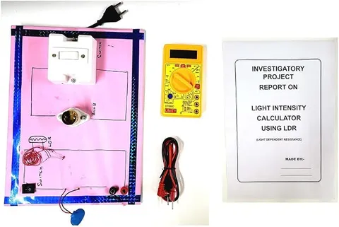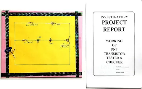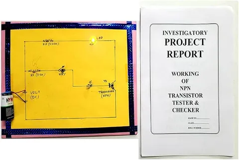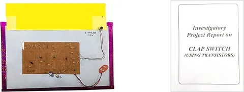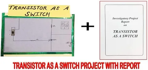
Engineered Wooden Transistor as a Switch Educational Circuit Board (Multicolour)
Code B07LD34TSW
- Paid for and delivered by Amazon. The current price and the delivery date for your PIN code are shown there.
- Sold by Gurukul Technicals Institute, Delhi.
- Need a different topic, a custom version or a school order? Ask on WhatsApp.
In this project guide
Physics
About this model
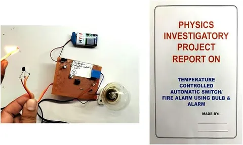
This educational circuit board demonstrates a transistor used as an electronic switch, where a small base current turns a larger load current fully on or fully off. It is the idea behind almost every automatic circuit, from street lights to computer chips. It is useful for Class 12 physics projects and for students starting electronics.
How it works
The science behind it
The idea the model demonstrates, in words you can use in your report and when you explain it.
A bipolar junction transistor has three terminals: emitter, base and collector. In an NPN silicon transistor, almost no collector current flows until the base-emitter junction is forward biased by about 0.7 V. This is the cut-off state, and the switch is OFF. When enough base current flows, the collector current rises until it is limited only by the load and the supply. This is saturation, and the switch is ON with only a small voltage left across the transistor. Between these two lies the active region, where IC = β IB and the transistor amplifies; a switch is designed to jump past it. The base resistor sets the base current so that the transistor saturates without being damaged. Because a tiny base current controls a much larger collector current, a weak sensor such as an LDR or a touch plate can drive an LED, buzzer or relay. The processor in a mobile phone contains billions of tiny transistor switches.
Make it yourself
Make a transistor switch circuit yourself
Build your own version from scratch, or use the steps to understand how the ready-made model is put together before you present it.
What you need 9
Step by step 8 steps
Find the transistor's emitter, base and collector from its datasheet, and connect the emitter to the battery negative.
Connect the LED and its 470 Ω resistor from the battery positive to the collector.
Connect the potentiometer's outer pins across the battery and its middle pin, through the 10 kΩ resistor, to the base.
Turn the knob slowly up from zero: the LED stays off until the base voltage nears about 0.7 V, then brightens quickly to full.
Measure the collector-emitter voltage with the LED fully off and fully on; it drops to a small value when the switch is ON.
Replace the LED with the relay coil, and fit the diode across the coil with its stripe to the positive side.
Wire the relay's contacts to switch the torch bulb and its own cells, so a tiny base current controls a separate circuit.
Turn the knob past the switching point and show the relay click and the bulb light.
Read this first
Safety first
Go through these points before you build or switch anything on. Younger students should do this with an adult.
- Always fit the diode across the relay coil, or the voltage spike at switch-off can destroy the transistor.
- Use batteries of 9 V or less on both sides of the relay; students must never connect relay contacts to mains, whatever the relay is rated for.
- Never connect the base directly to the battery without its resistor.
- Solder only with an adult, and heat the transistor's legs briefly so it is not damaged.
Troubleshooting
If something does not work
The usual problems with this model and how to fix them. Open a problem to see the fix.
The LED is always on
The collector and emitter may be swapped, or the transistor is damaged. Check the pin order and test it with the multimeter's diode range.
The LED never comes on
Check the base resistor and potentiometer wiring, and that the LED faces the right way.
The relay chatters near the switching point
The base voltage is sitting at the edge between off and on. Turn the knob firmly past the point; a real switch circuit is designed to jump straight through.
The transistor gets warm
It is being held between off and on, or the load draws too much current. Turn it fully on or off and check the load.
Exhibition day
How to present it
A running order for the exhibition table or the practical, step by step.
Show the load switching on and off and say which state, cut-off or saturation, each one is.
Measure the voltage between collector and emitter in both states with a multimeter.
Explain why a small base current can control a much larger collector current.
Draw the NPN symbol and explain what the arrow on the emitter shows.
Practice
Viva questions
Practice questions on this model, with short answers. Try each one aloud before you open the answer.
What are the two states of a transistor used as a switch?
Cut-off, when it is OFF and almost no collector current flows, and saturation, when it is fully ON.
What base-emitter voltage is needed to turn on a silicon transistor?
About 0.7 V.
Why is a resistor placed in the base circuit?
It limits the base current so the transistor is driven into saturation safely without being damaged.
What is current gain β?
β is the ratio of collector current to base current, IC/IB, in the active region.
Project file
Project file outline
The headings of the project file, in order. Give each heading its own section and write it in your own words.
Free ebook: Writing a Science Project FileContents
- Aim: to show how a transistor works as an electronic switch
- Structure of an NPN transistor and its three terminals
- Cut-off, active and saturation regions
- Circuit diagram of the transistor switch and how it works
- Observation table: base voltage, LED state and collector-emitter voltage
- Switching a relay, and why the diode is needed
- Uses: automatic street lights, alarms and logic circuits
- Precautions for the transistor and relay, and conclusion
Buying checklist
Before you buy
What to check before you order the model, and what to do when it arrives.
1Before you order
- Check in the listing what input switches the transistor on the board (a knob, a button or a sensor), so your file describes the real model.
- See whether a battery is mentioned in the listing; keep a fresh 9 V battery ready if not.
- Keep the box, and protect the transistor's legs from being bent.
- Check the delivery date for your PIN code on the marketplace, and order well before the exhibition or practical.
- Practise explaining it. Judges ask what the model shows and why; knowing the science matters as much as the model. The viva questions above are a good place to start.
2When it arrives
- Test it when it arrives and note the point at which it switches.
Next steps
Take it further
Ways to turn this model into a bigger investigation or a stronger exhibition entry.
Replace the potentiometer with an LDR divider to make an automatic night light.
Measure collector current against base voltage with a multimeter, plot it, and mark the three regions.
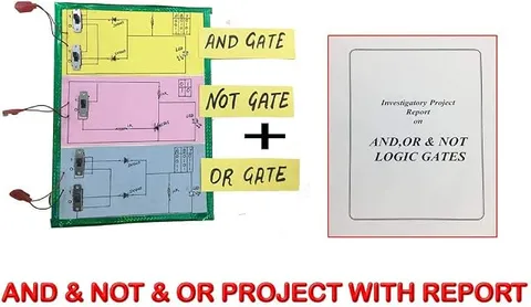
Use transistor switches to build NOT and NOR gates and show their truth tables.
Audience
Who it suits
Class 12 physics investigatory projects, and introductory electronics practicals in ITI, diploma and engineering courses.
- SubjectPhysics
Free to read
Free ebooks for this topic
Free PDF ebooks from Gurukul Technicals Institute on the science, the making and the presenting of projects like this one.
- Free PDF ebook
Electricity and Magnetism Experiments
Hands-on experiments with cells, wires, bulbs and magnets
- Free PDF ebook
Physics Working Models Explained
Twenty classic models, how each works and how to make it
- Free PDF ebook
Your Science Exhibition Guide
Choose a project, build it, present it and answer the judges with confidence
- Free PDF ebook
Writing a Science Project File
How to write the report, from the cover page to the bibliography