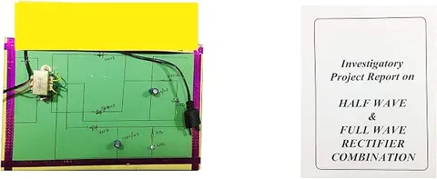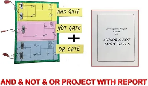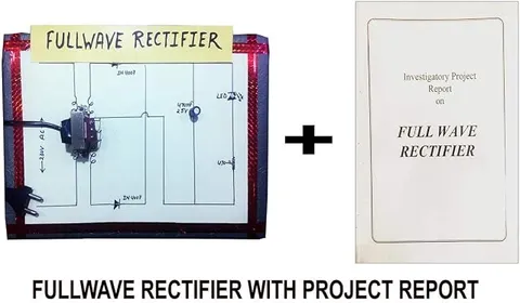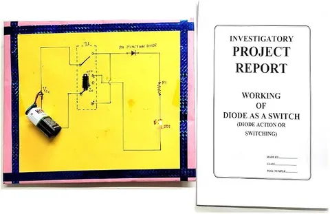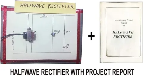
Generic Engineered Wood Half Wave Rectifier Educational Circuit Board (Multicolour)
Code B07H5MSSNQ
- Paid for and delivered by Amazon. The current price and the delivery date for your PIN code are shown there.
- Sold by Gurukul Technicals Institute, Delhi.
- Need a different topic, a custom version or a school order? Ask on WhatsApp.
In this project guide
Physics
About this model
This educational circuit board demonstrates a half wave rectifier, the simplest way to convert AC into DC, using a single diode. With only one diode and one load to trace, it makes a clear first step before moving on to full wave and bridge circuits. It is suited to Class 12 physics practicals and investigatory projects.
How it works
The science behind it
The idea the model demonstrates, in words you can use in your report and when you explain it.
A half wave rectifier uses one p-n junction diode in series with the load. During the positive half of the AC cycle the diode is forward biased and current flows; during the negative half it is reverse biased and blocks almost all current. The output is therefore a set of positive humps separated by gaps. For an ideal diode, the average (DC) value of this output is Vm/π, about 0.318 times the peak voltage Vm, and its ripple factor is about 1.21, which means the output is far from smooth. With a plain resistive load, the diode must withstand a peak inverse voltage equal to Vm during the off half. A real silicon diode also drops about 0.7 V while conducting, so the output peak is slightly lower than the input peak. Half wave rectifiers are cheap and simple, so they are used where smoothness matters little and the current drawn is small.
Make it yourself
Make a half wave rectifier board yourself
Build your own version from scratch, or use the steps to understand how the ready-made model is put together before you present it.
What you need 8
Step by step 9 steps
Fix the AC input terminals on the left of the board and the DC output terminals on the right, and label them.
Connect the diode from one input terminal to the positive output terminal, with its stripe (cathode) facing the output.
Join the other input terminal straight to the negative output terminal.
Connect the load resistor across the output, and the LED with its resistor beside it, long leg to the positive side.
Connect the capacitor through its switch across the output, stripe to the negative side.
Check the circuit, then let an adult connect the AC adapter and plug it in.
Measure the AC input on the multimeter's AC range and work out the peak value as about 1.41 times that reading.
Measure the DC output with the capacitor switched off and then on, and compare both readings with the peak value.
Unplug, turn the diode round, and power it again: the output now reads negative, showing that the diode decides which half of the wave passes.
Read this first
Safety first
Go through these points before you build or switch anything on. Younger students should do this with an adult.
- Only a ready-made low-voltage AC adapter is used, plugged in by an adult; students never wire anything to mains.
- Unplug the adapter before reversing the diode or changing any part, and fit the capacitor the right way round.
- When the diode is reversed, switch the capacitor out first, because an electrolytic capacitor must never see a reversed voltage.
- Keep the board on a dry table, and solder only with an adult.
Troubleshooting
If something does not work
The usual problems with this model and how to fix them. Open a problem to see the fix.
The output reads zero
Check that the adapter's label says AC output and that it is switched on, then test the diode with the multimeter's diode range.
The output reads about the same as the input on the AC range
The diode may be shorted or bypassed by a stray wire or solder bridge. Test it and check the board.
The DC reading is lower than I calculated
The diode drops about 0.7 V and the meter shows an average of the humps; this is normal and worth explaining in your file.
The LED does not glow
It may be reversed relative to the diode; turn it round, and check its resistor.
Exhibition day
How to present it
A running order for the exhibition table or the practical, step by step.
Show the input and output on a CRO if available, and point out that every second half cycle is missing.
Compare the AC input and DC output readings on a multimeter and explain why the DC value is only about 0.45 times the AC reading.
Ask the judges what the output would look like if the diode were reversed (negative humps), then explain.
Point to the band on the diode and explain how it marks the cathode and the direction of current.
Practice
Viva questions
Practice questions on this model, with short answers. Try each one aloud before you open the answer.
Why is it called a half wave rectifier?
Because it uses only one half of each AC cycle; the other half is blocked by the diode.
What is the average output of an ideal half wave rectifier?
Vdc = Vm/π, which is about 0.318 times the peak input voltage.
What is peak inverse voltage?
It is the maximum reverse voltage the diode must withstand when it is not conducting. For a half wave rectifier with a resistive load it equals Vm.
What is the ripple frequency of a half wave rectifier on 50 Hz mains?
50 Hz, because there is one output hump for every AC cycle.
Project file
Project file outline
The headings of the project file, in order. Give each heading its own section and write it in your own words.
Free ebook: Writing a Science Project FileContents
- Aim: to convert AC into DC using a single diode
- Forward and reverse bias of a p-n junction diode
- Circuit diagram and working of the half wave rectifier
- Input sine wave and output humps, drawn one above the other
- Observation table: AC input, calculated peak, and DC output with and without the capacitor
- Average value, ripple factor and peak inverse voltage
- Why half wave rectification wastes half the input
- Precautions with the AC supply and the capacitor, and conclusion
Buying checklist
Before you buy
What to check before you order the model, and what to do when it arrives.
1Before you order
- Check what supply the board needs; if it uses AC, plan for an adult to connect a low-voltage AC adapter.
- Ask your teacher whether a half wave board is enough or whether a full wave comparison is expected.
- Keep the box, and protect the components from being bent on the way to school.
- Check the delivery date for your PIN code on the marketplace, and order well before the exhibition or practical.
- Practise explaining it. Judges ask what the model shows and why; knowing the science matters as much as the model. The viva questions above are a good place to start.
2When it arrives
- Test it soon after it arrives and keep your readings for the file.
Next steps
Take it further
Ways to turn this model into a bigger investigation or a stronger exhibition entry.
Look at the output on an oscilloscope in the school lab with and without the capacitor, and sketch both.
Try capacitors of several values and plot capacitance against DC output.
Build a bridge rectifier on a second board and compare the two outputs.
Audience
Who it suits
Class 12 physics practicals on semiconductor diodes, and introductory electronics labs in ITI, diploma and engineering courses.
- SubjectPhysics
Free to read
Free ebooks for this topic
Free PDF ebooks from Gurukul Technicals Institute on the science, the making and the presenting of projects like this one.
- Free PDF ebook
Electricity and Magnetism Experiments
Hands-on experiments with cells, wires, bulbs and magnets
- Free PDF ebook
Physics Working Models Explained
Twenty classic models, how each works and how to make it
- Free PDF ebook
Your Science Exhibition Guide
Choose a project, build it, present it and answer the judges with confidence
- Free PDF ebook
Writing a Science Project File
How to write the report, from the cover page to the bibliography