- Physics
- Ready-made model
PNP Transistor Checker and Tester Physics Working Model Educational Science Project
Code B0C3H7739S
- Paid for and delivered by Amazon. The current price and the delivery date for your PIN code are shown there.
- Sold by Gurukul Technicals Institute, Delhi.
- Need a different topic, a custom version or a school order? Ask on WhatsApp.
In this project guide
Ready-made model
About this model
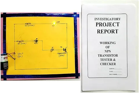
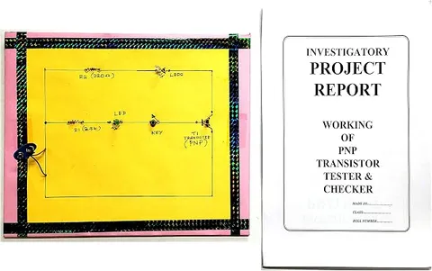
This PNP transistor checker is a working model for finding out whether a PNP transistor is good or faulty. It also helps students understand how a PNP transistor must be connected, with its emitter towards the positive side, before it will conduct.
How it works
The science behind it
The idea the model demonstrates, in words you can use in your report and when you explain it.
A transistor is made of three layers of semiconductor. In a PNP transistor a thin n-type base is sandwiched between a p-type emitter and a p-type collector, so it contains two p-n junctions, emitter-base and collector-base. Its main charge carriers are holes. To conduct, the emitter-base junction must be forward biased, which means the base is held about 0.7 V below the emitter for a silicon device, while the collector-base junction is reverse biased. A small base current then lets a much larger current flow from emitter to collector, and the currents are related by IE = IB + IC. A checker uses this: a good transistor switches an indicator on only when its base is biased correctly. If the indicator stays on all the time, the transistor is probably shorted; if it never comes on, a junction is probably open. In the circuit symbol, the arrow on the emitter points inwards.
Make it yourself
Make a PNP transistor tester yourself
Build your own version from scratch, or use the steps to understand how the ready-made model is put together before you present it.
What you need 8
Step by step 8 steps
Connect the E clip to the positive rail of the cell pack, because a PNP's emitter must be the most positive terminal.
Connect the C clip through the 330 Ω resistor and the LED to the negative rail, with the LED's shorter leg towards negative.
Connect the B clip through the 10 kΩ resistor and the push button to the negative rail, so pressing the button pulls the base below the emitter.
Check the transistor's pin order in its datasheet, clip it in, switch on, and look at the LED before pressing anything: it should stay dark.
- Press the button
A good PNP transistor conducts and the LED lights; release it and the LED goes out.
- Read the results
An LED that lights without pressing means a collector-emitter short, and one that never lights means an open junction or a wrong pin order.
Confirm with the multimeter's diode range: with the black probe on the base, the emitter and collector should each read about 0.6 to 0.7 V, and with the probes reversed there should be no reading.
Put the NPN transistor in the tester and show that it does not light, because it needs the opposite polarity.
Read this first
Safety first
Go through these points before you build or switch anything on. Younger students should do this with an adult.
- Use only the small cell pack; never test transistors on an adapter or the mains.
- Keep the 10 kΩ resistor in the base line and the 330 Ω resistor in the LED line, so a shorted transistor cannot draw a large current.
- Switch off before inserting or removing a transistor.
- Solder only with an adult.
Troubleshooting
If something does not work
The usual problems with this model and how to fix them. Open a problem to see the fix.
The LED never lights, even with a new transistor
Check that its legs match E, B and C, since pin orders differ between types, that E goes to positive, and that the LED is the right way round.
The LED lights as soon as a transistor is inserted
That transistor is probably shorted between collector and emitter. Confirm it with the multimeter, and check the tester again with a known good one.
The LED is very dim when the button is pressed
The transistor may have very low gain, or the cells are weak. Compare it with a known good transistor using fresh cells.
The LED flickers when I touch the transistor's legs
Your fingers are letting a little current into the base. Do not touch the legs during a test; hold the board by its edges.
Exhibition day
How to present it
A running order for the exhibition table or the practical, step by step.
Draw the PNP symbol on a chart and label the emitter, base and collector.
Test a known good PNP transistor first, then a faulty one, and compare the results.
Explain why the supply polarity for a PNP transistor is the opposite of that for an NPN.
Keep the pin diagram of the transistor you test on display, because pin order differs between types.
Practice
Viva questions
Practice questions on this model, with short answers. Try each one aloud before you open the answer.
What are the majority charge carriers in a PNP transistor?
Holes.
Which way does the emitter arrow point in the PNP symbol?
Inwards, towards the base. It shows the direction of conventional current through the emitter.
What is the relation between the emitter, base and collector currents?
IE = IB + IC, so the emitter current is the sum of the base and collector currents.
How must a PNP transistor be biased to conduct?
The emitter-base junction must be forward biased and the collector-base junction reverse biased.
Project file
Project file outline
The headings of the project file, in order. Give each heading its own section and write it in your own words.
Free ebook: Writing a Science Project FileContents
- Aim: to make a tester that shows whether a PNP transistor is good or faulty
- Structure of a PNP transistor and its two p-n junctions
- Biasing a PNP transistor, and why its emitter goes to positive
- Circuit diagram of the tester and how it works
- Construction
- Observation table: transistors tested, LED with and without the button, and the verdict
- Multimeter diode-test readings compared with the tester's results
- Common faults: shorted and open junctions
- Conclusion and precautions
Buying checklist
Before you buy
What to check before you order the model, and what to do when it arrives.
1Before you order
- Check that a transistor tester suits your class and the chapter on semiconductor devices.
- Read the listing for the battery it needs, and whether any transistors to test are mentioned; do not assume they are supplied.
- Buy a few PNP transistors of a common type to test, including at least one known to be good.
- Keep the box so the socket or clips are not bent.
- Check the delivery date for your PIN code on the marketplace, and order well before the exhibition or practical.
2When it arrives
- When it arrives, try it with a good transistor first so you trust its results in the viva.
Next steps
Take it further
Ways to turn this model into a bigger investigation or a stronger exhibition entry.
Add a switch that reverses the supply and the LED, so the same board can test both PNP and NPN transistors.
Insert a good transistor with emitter and collector swapped and show that it conducts only weakly, then explain why the two ends are not interchangeable.
With an adult, collect old transistors from broken gadgets and sort them into good and faulty with your tester.
Audience
Who it suits
Class 11 and 12 physics students, and ITI or diploma electronics learners who are studying transistors.
- SubjectPhysics
- TypeReady-made model
Free to read
Free ebooks for this topic
Free PDF ebooks from Gurukul Technicals Institute on the science, the making and the presenting of projects like this one.
- Free PDF ebook
Physics Working Models Explained
Twenty classic models, how each works and how to make it
- Free PDF ebook
Your Science Exhibition Guide
Choose a project, build it, present it and answer the judges with confidence
- Free PDF ebook
Writing a Science Project File
How to write the report, from the cover page to the bibliography
- Free PDF ebook
Viva Questions for Science Projects
How to answer examiner questions, with sample questions for popular projects