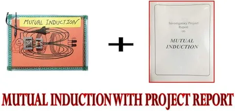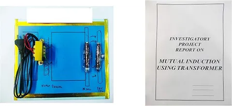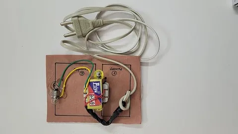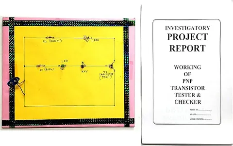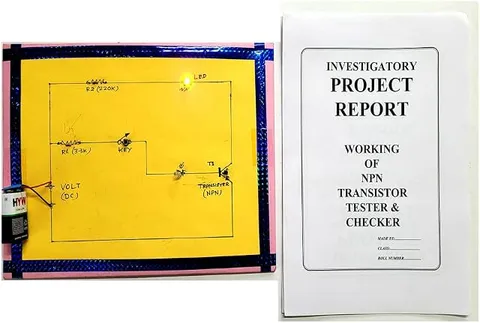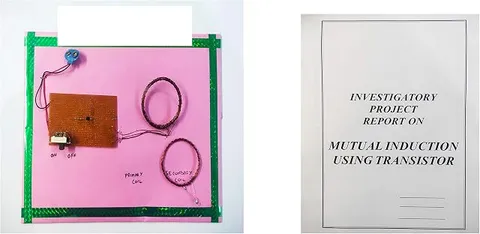
Mutual Induction Using Transistor Educational Circuit Board, Multicolor
Code B082YH12PH
- Paid for and delivered by Amazon. The current price and the delivery date for your PIN code are shown there.
- Sold by Gurukul Technicals Institute, Delhi.
- Need a different topic, a custom version or a school order? Ask on WhatsApp.
In this project guide
Physics
About this model
This circuit board demonstrates mutual induction, where a changing current in one coil produces a voltage in a nearby coil without any wire joining them. A transistor is used to create the changing current that induction needs, which is the key idea students must understand. It is a clear Class 12 level model of how energy passes between coils.
How it works
The science behind it
The idea the model demonstrates, in words you can use in your report and when you explain it.
Mutual induction happens when two coils are placed close together. A current in the first (primary) coil sets up a magnetic field, part of which passes through the second (secondary) coil. If the primary current changes, the flux through the secondary changes and an EMF is induced in it. The induced EMF is e = −M (dI/dt), where M is the mutual inductance, measured in henry (H), and the minus sign comes from Lenz's law. A steady direct current produces a steady field and induces nothing. That is why a transistor is used: wired as an oscillator, it switches the primary current on and off very rapidly, so the flux keeps changing and a load on the secondary, such as an LED, can glow. M increases with more turns, a larger coil area, a smaller gap and an iron core. Wireless phone chargers use the same principle.
Make it yourself
Make a mutual induction model with a transistor yourself
Build your own version from scratch, or use the steps to understand how the ready-made model is put together before you present it.
What you need 9
Step by step 8 steps
- Wind the primary coil
Hold two wires together and wind about 15 turns on the former, giving two coils side by side. Join the end of one wire to the start of the other to make a centre tap.
Scrape the enamel off every wire end with sandpaper until bright copper shows, and check each winding for continuity with the multimeter.
Connect the centre tap to battery positive, one outer end to the transistor's collector, and the other outer end through the 1 kΩ resistor to its base. Connect the emitter to negative (check the transistor's pin diagram).
- Wind the secondary coil
About 30 turns of a single wire on the same size former. Scrape its ends and connect the LED across them.
Switch on and hold the secondary coil just above the primary, parallel to it. The LED should glow even though no wire joins the two coils.
If the LED does not glow, switch off and swap the two outer primary ends going to the collector and the base; the feedback must be the right way round for the circuit to oscillate.
Lift the secondary slowly and note the distance at which the LED dims and goes out, then tilt it to show that the angle matters too.
Fix the primary circuit on the base, label the primary and secondary coils, and draw the circuit beside them.
Read this first
Safety first
Go through these points before you build or switch anything on. Younger students should do this with an adult.
- Use only AA cells (up to 6 V); never connect the coils to mains or to an adapter's insides.
- The transistor gets hot if the circuit is not oscillating; switch off and fix the wiring rather than leaving it on.
- Remove the enamel with sandpaper, not a blade, and solder only with an adult.
- Switch off between demonstrations, as the cells and transistor warm up with long use.
Troubleshooting
If something does not work
The usual problems with this model and how to fix them. Open a problem to see the fix.
The LED on the secondary coil does not glow at all
The circuit is probably not oscillating. Swap the coil ends at the collector and base, scrape the wire ends again, and recheck the transistor's pins.
The transistor gets hot quickly
It is stuck on instead of switching. Check the feedback connection and the 1 kΩ base resistor, and use fresh cells, never a higher voltage.
The LED glows only when the coils touch
Add more turns to the secondary, make both coils the same diameter, and keep them parallel and centred over each other.
It was bright at first but is now dim
The cells are running down, since this circuit draws a steady current. Fit fresh cells and switch off when not demonstrating.
Exhibition day
How to present it
A running order for the exhibition table or the practical, step by step.
Move the secondary coil slowly away from the primary, if the board allows, and show the output weakening with distance.
Explain on a chart why the circuit would not work with a steady DC current alone.
Point to the transistor and describe its job as a fast electronic switch.
Connect the demonstration to a real use such as wireless phone charging.
Practice
Viva questions
Practice questions on this model, with short answers. Try each one aloud before you open the answer.
What is mutual induction?
It is the production of an EMF in one coil due to a change of current in a neighbouring coil.
Why is a transistor needed in this circuit?
A battery gives steady DC, which cannot induce an EMF; the transistor oscillator makes the primary current change continuously.
What is the SI unit of mutual inductance?
The henry (H).
On what factors does mutual inductance depend?
On the number of turns, the area of the coils, the distance and alignment between them, and the material of the core.
Project file
Project file outline
The headings of the project file, in order. Give each heading its own section and write it in your own words.
Free ebook: Writing a Science Project FileContents
- Aim: to show mutual induction between two coils using a transistor oscillator
- Introduction: Faraday's discovery of induction and wireless charging today
- Materials and circuit diagram of the oscillator and the two coils
- Theory: e = −M (dI/dt), Lenz's law, and why a steady current induces nothing
- How the transistor makes the primary current change rapidly
- Procedure for winding and connecting the coils
- Observations: LED brightness at different distances and angles (table)
- Applications: transformers, wireless chargers and induction cooktops
- Conclusion, precautions and bibliography
Buying checklist
Before you buy
What to check before you order the model, and what to do when it arrives.
1Before you order
- Electromagnetic induction is a Class 12 topic; check that it matches your syllabus and what your teacher expects from a working model.
- Check in the listing whether batteries and a report are included.
- Find out by testing how far apart the coils can be for the indicator to work, so you can demonstrate confidently.
- Keep the box to protect the coils from being bent or crushed.
- Check the delivery date for your PIN code on the marketplace, and order well before the exhibition or practical.
- Practise explaining it. Judges ask what the model shows and why; knowing the science matters as much as the model. The viva questions above are a good place to start.
2When it arrives
- Test it on arrival and again a few days before the practical or exhibition, and carry spare cells.
Next steps
Take it further
Ways to turn this model into a bigger investigation or a stronger exhibition entry.
Measure the secondary voltage on the multimeter's AC range at different distances and plot it against distance.
Slide a ferrite rod or soft iron core through both coils and show how it increases the coupling.
Change the number of secondary turns and compare the output, linking it to the transformer turns ratio.
Audience
Who it suits
Suits Class 12 physics investigatory projects on electromagnetic induction and first-year engineering or polytechnic electronics labs.
- SubjectPhysics
Free to read
Free ebooks for this topic
Free PDF ebooks from Gurukul Technicals Institute on the science, the making and the presenting of projects like this one.
- Free PDF ebook
Electricity and Magnetism Experiments
Hands-on experiments with cells, wires, bulbs and magnets
- Free PDF ebook
Physics Working Models Explained
Twenty classic models, how each works and how to make it
- Free PDF ebook
Your Science Exhibition Guide
Choose a project, build it, present it and answer the judges with confidence
- Free PDF ebook
Writing a Science Project File
How to write the report, from the cover page to the bibliography