- Physics
- Ready-made model
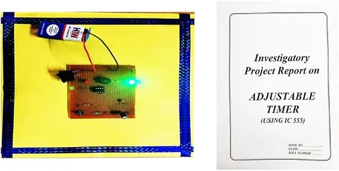
Adjustable Timer Using IC 555 Physics Working Model Educational Science Project
Code B0BN2KGJJ3
- Paid for and delivered by Amazon. The current price and the delivery date for your PIN code are shown there.
- Sold by Gurukul Technicals Institute, Delhi.
- Need a different topic, a custom version or a school order? Ask on WhatsApp.
In this project guide
Ready-made model
About this model
This adjustable timer is built around the popular 555 timer IC and keeps its output on for a set time that can be changed. It shows students how an electronic circuit measures time using nothing more than a resistor and a capacitor.
How it works
The science behind it
The idea the model demonstrates, in words you can use in your report and when you explain it.
In a timer circuit, the 555 IC is used in monostable mode: a short trigger pulse makes its output go HIGH, and the output stays HIGH for a fixed time before returning to LOW on its own. That time is set by a resistor R and a capacitor C, using T = 1.1 × R × C, with R in ohms, C in farads and T in seconds. During this time the capacitor charges through the resistor; when its voltage reaches two-thirds of the supply voltage, the IC ends the pulse and discharges the capacitor. Using a variable resistor (potentiometer) for R makes the timer adjustable. For example, with R = 100 kΩ and C = 100 µF, T = 1.1 × 100,000 × 0.0001 = 11 seconds. Staircase light switches in apartment buildings, which turn off by themselves after a minute or two, use the same timing idea.
Make it yourself
Make an adjustable 555 timer yourself
Build your own version from scratch, or use the steps to understand how the ready-made model is put together before you present it.
What you need 9
Step by step 8 steps
Fit the 555 in its socket, connect pin 8 to positive and pin 1 to negative, and fit the 10 nF capacitor from pin 5 to negative.
Connect pin 4 to positive through a 10 kΩ pull-up, with the reset button from pin 4 to negative, so pressing it stops the timer.
Connect pin 2 to positive through the other 10 kΩ pull-up, with the start button from pin 2 to negative; a quick press gives the trigger pulse.
Connect the 10 kΩ resistor and the potentiometer in series from positive to pin 7, join pin 7 to pin 6, and connect the 100 µF capacitor from pin 6 to negative, with its negative leg to negative.
Connect pin 3 through the 470 Ω resistor to the LED's longer leg, and the LED's shorter leg to negative.
Switch on, press start, and time with the stopwatch how long the LED stays on.
Compare your times with T = 1.1 × R × C: with 100 µF, the time runs from about 1 second at the knob's lowest setting to nearly two minutes at its highest.
- Calibrate the card dial
Set the knob, time the LED, and write that time at the knob's position, so the timer can be set by reading the dial.
Read this first
Safety first
Go through these points before you build or switch anything on. Younger students should do this with an adult.
- Use only the 9 V battery; this timer must not switch anything on the mains.
- Fit the electrolytic capacitor the right way round, with a voltage rating above 9 V.
- Check the IC's notch before switching on, and switch off if it gets warm.
- Solder only with an adult.
Troubleshooting
If something does not work
The usual problems with this model and how to fix them. Open a problem to see the fix.
The LED stays on and never goes off
The start button may be stuck or pin 2 may have no pull-up, so the timer keeps re-triggering. At the very top of the knob's range, a leaky capacitor may also never reach two-thirds of the supply; try a new capacitor.
The timer starts by itself when switched on
Many 555 circuits give one pulse at power-up. Press reset once after switching on.
The times do not match the formula
Electrolytic capacitors often differ by 20% or more from their marked value and leak slightly. Calibrate the dial by timing, not by calculation.
The LED never lights
Check that pin 4 is held at positive by its pull-up, that the LED is the right way round, and that the start button really pulls pin 2 to negative.
Exhibition day
How to present it
A running order for the exhibition table or the practical, step by step.
Set the control to two different positions and time the output with a stopwatch to show the change.
Write T = 1.1 × R × C on a chart and work through one example.
Explain what happens when the capacitor charges to two-thirds of the supply voltage.
Give an everyday example, such as the staircase light timer in an apartment block.
Practice
Viva questions
Practice questions on this model, with short answers. Try each one aloud before you open the answer.
In which mode does the 555 work in a timer circuit?
Monostable mode, in which one trigger gives one output pulse of fixed length.
What is the formula for the time period of a 555 monostable?
T = 1.1 × R × C, with R in ohms, C in farads and T in seconds.
How is the timer made adjustable?
A variable resistor is used in place of a fixed one, so changing its setting changes R and therefore the time T.
What happens to the time if the capacitor value is doubled?
The time doubles, because T is directly proportional to C.
Project file
Project file outline
The headings of the project file, in order. Give each heading its own section and write it in your own words.
Free ebook: Writing a Science Project FileContents
- Aim: to make an adjustable timer with the 555 IC and study how R and C set the time
- The 555 in monostable mode: trigger, threshold and discharge
- Charging a capacitor through a resistor
- The formula T = 1.1RC, with a worked example
- Circuit diagram and construction
- Observation table: dial position, measured time and calculated time
- Graph of time against resistance, and sources of error
- Uses of timers: kitchen timers, staircase lights and quiz buzzers
- Conclusion
Buying checklist
Before you buy
What to check before you order the model, and what to do when it arrives.
1Before you order
- Check with your teacher that a 555 timer project suits your class and syllabus.
- Read the listing for the supply it needs and anything else it mentions; do not assume a battery is included.
- Test it again a few days before the exhibition and carry a spare battery.
- Keep the box and padding so the knob and components are not damaged.
- Check the delivery date for your PIN code on the marketplace, and order well before the exhibition or practical.
- Practise explaining it. Judges ask what the model shows and why; knowing the science matters as much as the model. The viva questions above are a good place to start.
2When it arrives
- When it arrives, time a few settings with a stopwatch so you can quote your own figures.
Next steps
Take it further
Ways to turn this model into a bigger investigation or a stronger exhibition entry.
Swap the 100 µF capacitor for 47 µF and 220 µF and show how the time range changes.
Add a transistor and a relay so the timer switches a separate low-voltage lamp, like a staircase light timer.
Measure the capacitor voltage every few seconds during one timing period and plot its charging curve.
Audience
Who it suits
Class 10 to 12 students and electronics beginners who want a practical project on timers and the 555 IC.
- SubjectPhysics
- TypeReady-made model
Free to read
Free ebooks for this topic
Free PDF ebooks from Gurukul Technicals Institute on the science, the making and the presenting of projects like this one.
- Free PDF ebook
Physics Working Models Explained
Twenty classic models, how each works and how to make it
- Free PDF ebook
Your Science Exhibition Guide
Choose a project, build it, present it and answer the judges with confidence
- Free PDF ebook
Writing a Science Project File
How to write the report, from the cover page to the bibliography