- Science
- Kit
- Class 10 to 12
Generic Educational Project Kit: Convertible Solar Circuit Model & Experiment, Physics Educational Investigatory Project for Students & Adults
Code B0DK2712KH
- Paid for and delivered by Amazon. The current price and the delivery date for your PIN code are shown there.
- Sold by Gurukul Technicals Institute, Delhi.
- Need a different topic, a custom version or a school order? Ask on WhatsApp.
In this project guide
Kit
About this kit
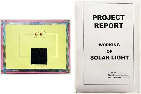
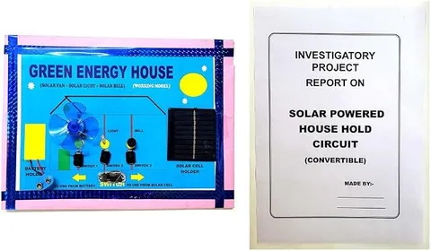
This educational kit is built around a solar circuit for experiments with sunlight and electricity. The word 'convertible' in the title suggests the circuit can be set up in more than one way, so check the listing for the exact experiments it supports. It suits students who want to explore how solar panels produce electricity and what changes their output.
How it works
The science behind it
The idea the kit demonstrates, in words you can use in your report and when you explain it.
A solar panel is made of solar cells that convert light into electricity through the photovoltaic effect, and its output depends on several things a student can test. The brighter the light and the more squarely it strikes the panel, the more current it gives, and shading even part of a panel can cut its output sharply. When cells or panels are connected in series, their voltages add while the current stays about the same; when they are connected in parallel, their currents add while the voltage stays the same. Electrical power is P = V × I, measured in watts. India is in the northern hemisphere, so fixed rooftop panels here are usually faced south and tilted at roughly the local latitude, about 28 degrees in Delhi, to collect the most sunlight over a year. Rooftop solar on homes and schools is now common across the country.
Make it yourself
Make a convertible series-parallel solar circuit yourself
Everything you need and the order to do it in. Tick off the materials as you collect them.
What you need 10
Step by step 9 steps
Fix the two panels side by side on the hinged stand so they tilt together, and mark 0°, 30°, 45°, 60° and 90° beside the hinge with the protractor.
Label the leads A+, A−, B+ and B−. Join A+ straight to the red output terminal and B− straight to the black output terminal.
Wire the DPDT switch. First pole: A− to the middle terminal, B+ to the 'series' end and the black output to the 'parallel' end. Second pole: B+ to the middle terminal, the red output to the 'parallel' end, and leave its 'series' end empty.
In sunlight, check the output with the multimeter: in series it should be about the sum of the two panel voltages, and in parallel about the same as one panel.
For each setting, measure the open-circuit voltage, then put the meter on its current range across the output for a moment only and read the current.
Connect the 100 Ω load, measure the voltage across it, and work out the power P = V² / R for series and for parallel.
Face the panels south with the compass and measure the output at each marked tilt angle around midday, keeping the switch setting the same.
Cover one cell of one panel with black card, then with thin paper, and compare how much the output falls in series and in parallel.
Connect the motor, and then the LED with its resistor, in each setting, in strong and in weak light, and note which setting runs each one better.
Read this first
Safety first
Go through these points before you build or switch anything on. Younger students should do this with an adult.
- Never look at the Sun while lining up the panels; aim them by watching their shadow instead.
- Take readings in short sessions with a cap and drinking water, and keep the panels and meter in shade between readings, as they get hot in direct sun.
- Hold the meter on its current range across the panels only for a moment, and never across a battery, which can blow the meter's fuse.
- Handle the panels by their edges and do not press or drop them; a cracked panel can have sharp edges.
Troubleshooting
If something does not work
The usual problems with this kit and how to fix them. Open a problem to see the fix.
The output reads almost zero in the series position
One panel is connected the wrong way round, so the two voltages cancel. Measure each panel on its own, check the labels, and make sure A− goes to B+ in series.
Series and parallel give the same reading
The switch is wired wrongly, often with a middle and an end terminal swapped. Trace each pole with the multimeter's continuity range in both switch positions.
The readings keep jumping about
Passing clouds, or your own shadow, change the light. Stand on the north side of the panels, wait for a steady sky, and take three readings to average.
The motor does not start although the voltage looks fine
A motor needs a burst of current to overcome friction when starting. Give the blade a gentle flick, try the parallel setting, use a lighter blade, or wait for brighter sun.
Exhibition day
How to present it
A running order for the exhibition table or the practical, step by step.
Tilt the panel at different angles to the light and show which angle gives the best output.
If the kit allows it, compare series and parallel connections and note the difference.
Cover part of the panel to show how shading affects the output.
If you have a multimeter, measure the voltage and current and work out the power using P = V × I.
Practice
Viva questions
Practice questions on this kit, with short answers. Try each one aloud before you open the answer.
What happens to the voltage when solar cells are connected in series?
The voltages add up, while the current stays roughly the same.
What happens when solar cells are connected in parallel?
The currents add up, while the voltage stays the same.
Why do rooftop solar panels in India usually face south?
India is in the northern hemisphere, so the Sun is in the southern part of the sky for most of the year.
Write the formula for electrical power.
P = V × I, where V is the voltage in volts and I is the current in amperes.
Project file
Project file outline
The headings of the project file, in order. Give each heading its own section and write it in your own words.
Free ebook: Writing a Science Project FileContents
- Aim: to compare the output of two solar panels joined in series and in parallel
- Introduction: the photovoltaic effect and how a solar cell works
- Theory: series voltages add, parallel currents add, and P = V × I
- Circuit diagram of the DPDT series-parallel changeover
- Observations: voltage, current and power in each setting
- Effect of tilt angle and of partial shading on the output
- Graph of power against tilt angle
- Applications: rooftop solar systems and why panels are wired in strings
- Precautions, sources of error and conclusion
Buying checklist
Before you buy
What to check before you order the kit, and what to do when it arrives.
1Before you order
- Check that renewable energy or current electricity is in your syllabus and that your teacher wants an experiment rather than a display model.
- Read the listing carefully for the experiments it supports and what it includes, since 'convertible' can mean different things.
- Exhibition halls are often too dim for solar panels, so record your outdoor readings in advance and ask whether a bright lamp may be used on the day.
- Keep the box and cover the panel faces so they are not scratched in transport.
- Check the delivery date for your PIN code on the marketplace, and order well before the exhibition or practical.
- Check whether it arrives assembled. The listing calls it a kit, so look at the photos and the box contents on the marketplace before you order.
2When it arrives
- Test it in sunlight as soon as it arrives, as indoor lighting is usually too weak for a fair reading.
Next steps
Take it further
Ways to turn this kit into a bigger investigation or a stronger exhibition entry.
Use several load resistors to plot a current-voltage curve and find the maximum power point.
Record the output every hour from morning to evening on one day and relate the curve to the Sun's height.
Test red, green and blue cellophane filters over the panels and explain the result with the photovoltaic effect.
Fit a bypass diode across each panel and show how it reduces the loss from shading in series.
Audience
Who it suits
Class 8 to 12 students, and adults, who want hands-on experiments with solar energy and simple circuits.
- ClassClass 10 to 12
- SubjectScience
- TypeKit
Free to read
Free ebooks for this topic
Free PDF ebooks from Gurukul Technicals Institute on the science, the making and the presenting of projects like this one.
- Free PDF ebook
Electricity and Magnetism Experiments
Hands-on experiments with cells, wires, bulbs and magnets
- Free PDF ebook
Physics Working Models Explained
Twenty classic models, how each works and how to make it
- Free PDF ebook
Investigatory Projects for Class 11 and 12
Topics, method and report structure for physics, chemistry and biology