- Physics
- DIY kit
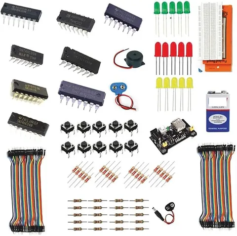
120+ Logic Gates DIY Kit NAND
Code B0FGV2RZL2
- Paid for and delivered by Amazon. The current price and the delivery date for your PIN code are shown there.
- Sold by Gurukul Technicals Institute, Delhi.
- Need a different topic, a custom version or a school order? Ask on WhatsApp.
In this project guide
DIY kit
About this kit
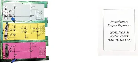
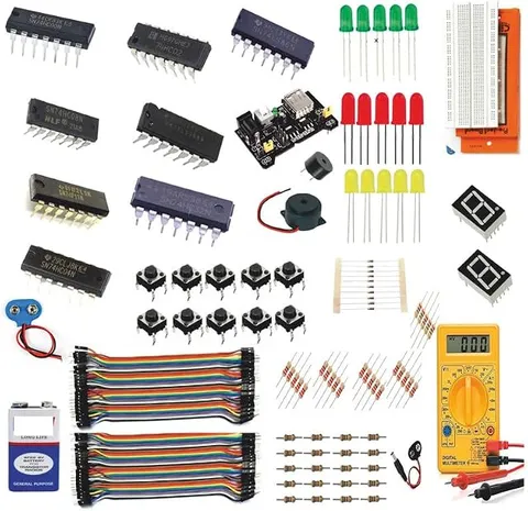
A do-it-yourself logic gates kit, listed as a 120+ kit, covering NAND, AND, OR, NOT, NOR, XOR and XNOR gates. It suits students who want to wire gates themselves and go beyond single gates to small circuits such as a half adder.
How it works
The science behind it
The idea the kit demonstrates, in words you can use in your report and when you explain it.
With seven gate types to build, this kit covers the whole family of basic logic. XOR gives 1 when its two inputs are different, and XNOR gives 1 when they are the same, so XNOR works as an equality checker. NAND alone is universal: joining both inputs of a NAND makes a NOT gate, a NAND followed by a NOT makes an AND, and NOT gates on both inputs of a NAND make an OR. That last step is De Morgan's theorem, which says (A·B)' = A' + B' and (A + B)' = A'·B'. Gates combine into useful circuits. A half adder adds two binary digits: the sum bit is A XOR B and the carry bit is A AND B, so 1 + 1 gives sum 0 and carry 1, which is 10 in binary, the number two. Chains of adders built from transistors are what let a calculator or computer do arithmetic.
Make it yourself
Make all seven logic gates and a half adder from NAND gates yourself
Everything you need and the order to do it in. Tick off the materials as you collect them.
What you need 8
Step by step 9 steps
- Build the 5 V supply
With the 7805's printed face towards you, the left pin takes the 9 V input, the middle pin goes to negative and the right pin gives 5 V. Put a 10 µF capacitor from input to negative and another from output to negative, and check for 5 V with the multimeter before fitting any chip.
Set up inputs A and B: each switch connects its line to 5 V, its 10 kΩ resistor holds the line at negative when the switch is off, and an LED with 330 Ω shows when the input is 1.
Fit the first 74HC00 across the centre gap with its notch to the left, pin 14 to 5 V and pin 7 to negative. Test one NAND gate: inputs on pins 1 and 2, output on pin 3 to an LED with 330 Ω.
Make NOT by joining both inputs of a NAND gate, and AND by following a NAND gate with a NAND-made NOT.
Make OR by putting a NAND-made NOT on each input and feeding both into a third NAND gate. This is De Morgan's theorem in wires: (A'·B')' = A + B.
Make NOR by adding a NAND-made NOT after your OR gate.
Make XOR from four NAND gates: gate 1 takes A and B; gate 2 takes A and gate 1's output; gate 3 takes B and gate 1's output; gate 4 takes the outputs of gates 2 and 3. Add a NAND-made NOT after it to get XNOR.
Check each NAND-built gate against its own IC. Note that the 74HC02 (NOR) has its outputs on pins 1, 4, 10 and 13, unlike the others.
- Make a half adder
The XOR output is the Sum and an AND made from NAND gates gives the Carry. Label the two output LEDs and show that 1 + 1 gives Sum 0, Carry 1, which is 10 in binary.
Read this first
Safety first
Go through these points before you build or switch anything on. Younger students should do this with an adult.
- Never connect a 74HC chip straight to the 9 V battery: these chips work only up to about 6 V, so always feed them through the regulator.
- The 7805 can get warm; if it becomes hot to touch, switch off and look for a short circuit or a chip fitted backwards.
- Fit and remove chips only with the power off, and touch a metal tap or window frame first to discharge static from your body.
- Keep loose chips and small parts away from young children.
Troubleshooting
If something does not work
The usual problems with this kit and how to fix them. Open a problem to see the fix.
Outputs change randomly or several LEDs are on that should be off
Unused inputs on these CMOS chips are floating. Connect every unused gate input to negative, and check that each chip has pin 14 at 5 V and pin 7 at negative.
The XOR made from NAND gates is wrong for one input combination
One wire to gate 2 or gate 3 is on the wrong input. Gate 1's output must go to both gate 2 and gate 3; trace each wire with the multimeter.
The regulator gets hot and its output is below 5 V
Something is drawing too much current: a chip in backwards, a wire shorting 5 V to negative, or an LED without its resistor. Switch off and check.
The half adder's Carry LED lights for 1 + 0
Your AND gate is missing its NOT stage, so it is really a NAND or an OR. Check that the Carry output comes after the NAND-made NOT.
Exhibition day
How to present it
A running order for the exhibition table or the practical, step by step.
Build and test a half adder, showing all four input combinations with their sum and carry outputs.
Show NAND as a universal gate by making NOT, AND and OR from NAND gates only.
Prove one of De Morgan's theorems live by comparing two truth tables that come out identical.
Keep your wiring neat and colour-coded so the judges can follow each connection.
Practice
Viva questions
Practice questions on this kit, with short answers. Try each one aloud before you open the answer.
What is the output of an XOR gate when both inputs are 1?
The output is 0, because XOR gives 1 only when the inputs are different.
State De Morgan's theorems.
The complement of a product equals the sum of the complements, (A·B)' = A' + B', and the complement of a sum equals the product of the complements, (A + B)' = A'·B'.
Which gates make a half adder?
An XOR gate gives the sum bit and an AND gate gives the carry bit.
How do you make a NOT gate from a NAND gate?
Join both inputs of the NAND gate together, so the output is always the complement of the single input.
Project file
Project file outline
The headings of the project file, in order. Give each heading its own section and write it in your own words.
Free ebook: Writing a Science Project FileContents
- Aim: to build all seven logic gates from NAND gates and use them to make a half adder
- Components and the 5 V regulated supply
- Symbols, Boolean expressions and truth tables of AND, OR, NOT, NAND, NOR, XOR and XNOR
- NAND as a universal gate: circuit diagrams for each gate built from NANDs
- De Morgan's theorems checked with the OR-from-NAND circuit
- Comparison of the NAND-built gates with the dedicated gate ICs
- The half adder: Sum and Carry, with its truth table
- Applications: adders in calculators, parity checkers and comparators
- Conclusion
Buying checklist
Before you buy
What to check before you order the kit, and what to do when it arrives.
1Before you order
- Check whether your syllabus or teacher wants gates built from ICs, from transistors or both, and whether a half adder is expected.
- Read the listing's parts list to see which ICs and how many come with the kit, and what power supply it expects.
- Build and test the circuits a week before the exhibition, and keep a spare battery.
- Check the delivery date for your PIN code on the marketplace, and order well before the exhibition or practical.
- Building it yourself: younger students should build with an adult, especially with motors, batteries and small parts.
2When it arrives
- When it arrives, sort the parts, read the number printed on each chip, and tick them off against the listing.
Next steps
Take it further
Ways to turn this kit into a bigger investigation or a stronger exhibition entry.
Build a full adder from two half adders and an OR gate, then chain two of them to add two 2-bit numbers.
Build every gate from NOR gates instead, and compare how many gates each method needs.
Make a 2-bit equality checker with XNOR gates, or a parity checker that lights when an odd number of switches are on.
Audience
Who it suits
Suits Class 11 and 12 computer science and physics projects, and diploma or engineering students learning digital electronics.
- SubjectPhysics
- TypeDIY kit
Free to read
Free ebooks for this topic
Free PDF ebooks from Gurukul Technicals Institute on the science, the making and the presenting of projects like this one.
- Free PDF ebook
Physics Working Models Explained
Twenty classic models, how each works and how to make it
- Free PDF ebook
Your Science Exhibition Guide
Choose a project, build it, present it and answer the judges with confidence
- Free PDF ebook
Writing a Science Project File
How to write the report, from the cover page to the bibliography