- Physics
- DIY kit
- Class 1 to 9
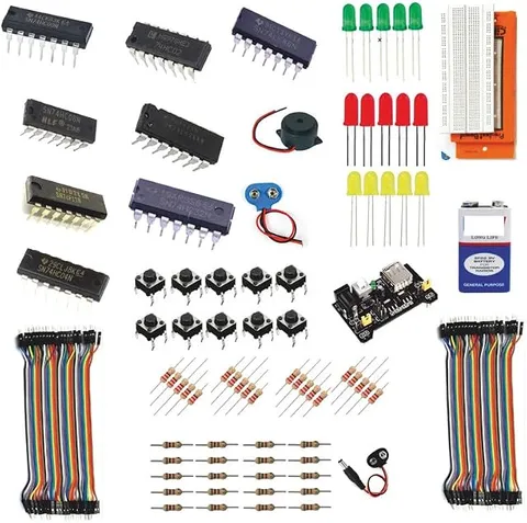
170+ Beginner Logic Gates DIY Kit NAND
Code B0FGV3BBLM
- Paid for and delivered by Amazon. The current price and the delivery date for your PIN code are shown there.
- Sold by Gurukul Technicals Institute, Delhi.
- Need a different topic, a custom version or a school order? Ask on WhatsApp.
In this project guide
DIY kit
About this kit
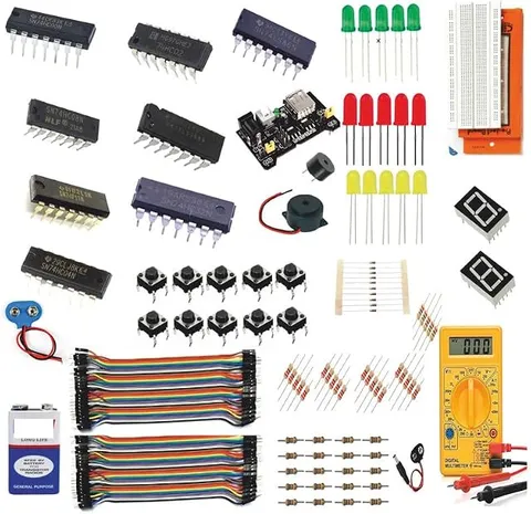
This is a beginner DIY kit for building logic gate circuits; the listing calls it a 170+ beginner kit and names the AND, OR, NOT, NAND, NOR, XOR and XNOR gates. Building each gate yourself and checking its truth table is one of the best ways to understand the digital logic behind computers, calculators and mobile phones.
How it works
The science behind it
The idea the kit demonstrates, in words you can use in your report and when you explain it.
Digital circuits work with only two states: 1 (HIGH, a voltage present) and 0 (LOW, no voltage). Each gate follows a fixed rule, shown in a truth table. An AND gate gives 1 only when all its inputs are 1 (Y = A·B); an OR gate gives 1 when any input is 1 (Y = A + B); a NOT gate inverts its single input. NAND and NOR are simply AND and OR followed by NOT. XOR gives 1 when its two inputs differ, and XNOR gives 1 when they are the same. NAND and NOR are called universal gates, because any other gate can be built using only one of them. De Morgan's theorems link the gates: NOT(A·B) = (NOT A) + (NOT B), and NOT(A + B) = (NOT A)·(NOT B). The two-way staircase switch at home behaves like an XOR or XNOR gate: flipping either switch changes the state of the light.
Make it yourself
Make all seven logic gates yourself on a breadboard
Everything you need and the order to do it in. Tick off the materials as you collect them.
What you need 9
Step by step 8 steps
Connect the supply to the breadboard's power rails, red for positive and blue for negative.
- Set up the two inputs
Each switch connects its line to positive, and a 10 kΩ resistor holds the line at negative when the switch is open.
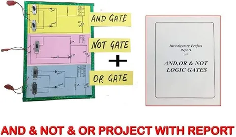
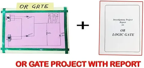
Make an OR gate from two diodes, anodes to the inputs and cathodes joined, with a 10 kΩ resistor from the joined point to negative. Feed that point through a 10 kΩ resistor to a transistor's base, with the emitter to negative and the LED and its 330 ohm resistor from positive to the collector.
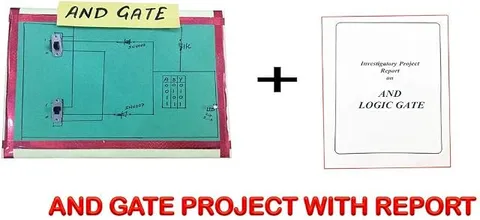
Make an AND gate from two transistors in series: the LED and its 330 ohm resistor from positive to the first transistor's collector, its emitter to the second transistor's collector, and the second emitter to negative. Feed A and B to the two bases through 10 kΩ resistors; current flows through the LED only when both are switched on.
- Make a NOT gate
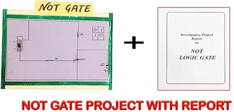
Input through 10 kΩ to a transistor's base, emitter to negative, collector to positive through 1 kΩ, with an LED and 330 ohm resistor from the collector to negative.
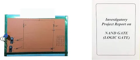
Make NAND with two transistors in series under one collector resistor, and NOR with two transistors side by side under one collector resistor.
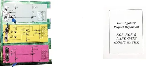
Build XOR from four NAND gates of the 74HC00, check it against the 74HC86, and add a NOT gate after it to make XNOR.
For each gate, try all four input combinations, note whether the LED is on (1) or off (0), and compare with its truth table.
Read this first
Safety first
Go through these points before you build or switch anything on. Younger students should do this with an adult.
- Keep to 6 V or less, and never connect the breadboard to a mains adapter that has been opened or modified.
- Fit every LED with a resistor, and insert ICs the right way round with the power off.
- Do not short the positive and negative rails, because batteries and wires heat up quickly.
- If you solder a permanent circuit, do it with an adult present.
Troubleshooting
If something does not work
The usual problems with this kit and how to fix them. Open a problem to see the fix.
The output LED is on with no input pressed
An input is floating. Check that each input has its 10 kΩ pull-down resistor to negative.
The LED never lights
It may be the wrong way round (the long leg goes towards positive), or it burnt out without a resistor. Test it on its own.
The IC gets hot
The supply is reversed or on the wrong pins. Switch off and check the pin diagram; on these 14-pin gate ICs, pin 14 is positive and pin 7 is negative.
The OR gate's LED stays on with no input pressed
A diode may be fitted backwards, or the 10 kΩ resistor from the joined cathodes to negative may be missing. The band on each diode must face the joined point.
Exhibition day
How to present it
A running order for the exhibition table or the practical, step by step.
Prepare a truth-table chart for all seven gates and verify each row live by switching the inputs and watching the output.
Show why NAND is universal by building a NOT gate (both inputs joined together) and then an AND gate from NAND gates only.
Finish with a half adder, using an XOR gate for the sum and an AND gate for the carry, to show how computers add binary numbers.
Label every input and output clearly, so an examiner can follow the circuit without tracing each wire.
Practice
Viva questions
Practice questions on this kit, with short answers. Try each one aloud before you open the answer.
Why are NAND and NOR gates called universal gates?
Because every other logic gate, and therefore any digital circuit, can be built using only NAND gates or only NOR gates.
When does an XOR gate give an output of 1?
An XOR gate gives 1 when its two inputs are different, that is, for the inputs 0, 1 and 1, 0.
Write De Morgan's two theorems.
NOT(A·B) equals (NOT A) + (NOT B), and NOT(A + B) equals (NOT A)·(NOT B).
How many rows does the truth table of a three-input gate have?
It has 2³ = 8 rows, one for each possible combination of the three inputs.
Project file
Project file outline
The headings of the project file, in order. Give each heading its own section and write it in your own words.
Free ebook: Writing a Science Project FileContents
- Aim: to build the basic, universal and special logic gates and verify their truth tables
- Components
- Binary logic, Boolean expressions and gate symbols
- Circuit diagrams for each gate
- Truth tables: expected and observed
- NAND and NOR as universal gates
- Checking De Morgan's theorems with the circuits
- Applications in computers and everyday electronics
- Conclusion
Buying checklist
Before you buy
What to check before you order the kit, and what to do when it arrives.
1Before you order
- Logic gates appear in computer science and in some physics syllabuses; check whether your teacher wants gates built from transistors, from ICs, or both.
- Read the listing's parts list for the ICs, transistors and power supply it names, so you know what you may need to buy separately.
- Check in the listing whether a guide or circuit book is included; if not, plan your circuits from your textbook first.
- Keep the box, with small parts in labelled bags, so nothing is lost before the exhibition.
- Check the delivery date for your PIN code on the marketplace, and order well before the exhibition or practical.
- Building it yourself: younger students should build with an adult, especially with motors, batteries and small parts.
2When it arrives
- Count and sort the parts when they arrive, and build one simple gate the same day to check the breadboard and LEDs.
Next steps
Take it further
Ways to turn this kit into a bigger investigation or a stronger exhibition entry.
Combine an XOR and an AND gate into a half adder, then two half adders into a full adder.
Make a simple burglar alarm or a voting machine using AND and OR logic.
Build every gate from NAND gates alone to prove that NAND is universal.
Audience
Who it suits
Suits Class 9 to 12 students learning Boolean logic for computer science or electronics projects, and beginners starting digital electronics.
- ClassClass 1 to 9
- SubjectPhysics
- TypeDIY kit
Free to read
Free ebooks for this topic
Free PDF ebooks from Gurukul Technicals Institute on the science, the making and the presenting of projects like this one.
- Free PDF ebook
Physics Working Models Explained
Twenty classic models, how each works and how to make it
- Free PDF ebook
Your Science Exhibition Guide
Choose a project, build it, present it and answer the judges with confidence
- Free PDF ebook
Writing a Science Project File
How to write the report, from the cover page to the bibliography