- Physics
- Ready-made model
- Printed report included
Series LCR Circuit Physics Electronics Working Model with Report
Code B0G2T8PSWB
- Paid for and delivered by Amazon. The current price and the delivery date for your PIN code are shown there.
- Sold by Gurukul Technicals Institute, Delhi.
- Need a different topic, a custom version or a school order? Ask on WhatsApp.
In this project guide
Ready-made model
About this model
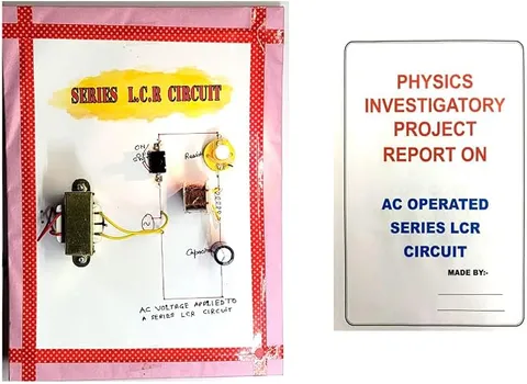
This physics working model is based on a resistor, an inductor and a capacitor connected in series to an alternating source, and is used to explain impedance and resonance. The listing says a report is included, which can help with the written part of an investigatory project.
How it works
The science behind it
The idea the model demonstrates, in words you can use in your report and when you explain it.
In a series LCR circuit with an AC source of frequency f, the inductor opposes the current with inductive reactance XL = 2πfL, and the capacitor with capacitive reactance XC = 1/(2πfC). These two act in opposite directions, so the total opposition, called impedance, is Z = √(R² + (XL − XC)²), and the current is I = V/Z. The voltage leads or lags the current by a phase angle φ, where tan φ = (XL − XC)/R. As the frequency is changed, there is one frequency at which XL = XC; this is resonance. Then Z = R, the current is at its maximum and the circuit behaves like a pure resistor. The resonant frequency is f₀ = 1/(2π√(LC)). A radio's tuning circuit uses this idea: turning the knob changes C until the circuit resonates with the station you want, such as an All India Radio channel.
Make it yourself
Make a series LCR circuit model yourself
Build your own version from scratch, or use the steps to understand how the ready-made model is put together before you present it.
What you need 8
Step by step 8 steps
Fix the choke, the resistor, the lamp holder and the capacitors on the base with screw terminals, and note the choke's markings for your report.
Join the choke, the resistor, the lamp and the capacitor bank one after another in a single series loop.
Connect the capacitors to each other in parallel through small switches, so you can add capacitance in steps of 1 to 2 µF.
Connect the low-voltage output leads of the AC adapter to the loop through a switch. An adult plugs the adapter into the socket; students handle only the low-voltage side.
Switch on with only the smallest capacitor in circuit: the lamp stays dark because the capacitor's reactance is large. Add capacitance one step at a time and watch for the setting where the lamp is brightest; that is resonance at the 50 Hz supply frequency.
Measure the AC voltage across the resistor, the choke and the capacitors at a few settings. Note that near resonance the choke and capacitor voltages can each be two or three times the supply, and the readings do not simply add up.
Record the capacitance and the voltage across the resistor (which shows the current) at every step, and plot current against capacitance to see the resonance peak.
Draw the circuit diagram and a phasor diagram on a chart beside the model.
Read this first
Safety first
Go through these points before you build or switch anything on. Younger students should do this with an adult.
- Only a low-voltage AC adapter is used, plugged in by an adult. Students must never open the adapter, wire a mains plug, or connect anything directly to a wall socket.
- Unplug the adapter from the socket before changing any connection on the board.
- Use only non-polarised capacitors; a polarised electrolytic capacitor on AC can overheat and burst.
- The choke and resistor can get warm, so switch off between readings and never leave the model running unattended.
Troubleshooting
If something does not work
The usual problems with this model and how to fix them. Open a problem to see the fix.
The lamp never gets clearly brighter at any setting
The capacitance range may not reach the value needed for resonance with your choke at 50 Hz. Add more capacitance in small steps, up to about 12 µF; a choke of 1 to 2 henries resonates at roughly 5 to 10 µF.
The lamp never lights
A terminal may be loose, the choke may have a broken winding, or the adapter may give DC instead of AC; a capacitor blocks DC completely. Check the adapter label says AC output.
A capacitor gets warm
It may be a polarised type or have too low a voltage rating. Ask an adult to unplug the adapter and replace it with a non-polarised capacitor of a higher rating.
The multimeter readings jump about
Make sure it is on the AC voltage range, hold the probes firmly on the terminals, and give the reading a few seconds to settle.
Exhibition day
How to present it
A running order for the exhibition table or the practical, step by step.
Write the impedance and resonance formulas on a chart and label every symbol with its unit.
If your setup lets you vary the frequency or the capacitance, show the current rising to a peak at resonance and falling on either side.
Sketch the phasor diagram with VL and VC pointing in opposite directions and VR in line with the current.
Relate the topic to radio tuning so the examiner sees a real use.
Practice
Viva questions
Practice questions on this model, with short answers. Try each one aloud before you open the answer.
What is resonance in a series LCR circuit?
It is the condition in which inductive reactance equals capacitive reactance, so the impedance is minimum (equal to R) and the current is maximum.
Write the formula for the resonant frequency.
f₀ = 1/(2π√(LC)), where L is the inductance in henry and C is the capacitance in farad.
What is the power factor at resonance?
It is 1, because the phase angle between voltage and current is zero.
Why does the reactance of an inductor increase with frequency?
Because XL = 2πfL; a faster-changing current produces a larger opposing emf in the coil.
Project file
Project file outline
The headings of the project file, in order. Give each heading its own section and write it in your own words.
The listing includes a printed project report: use this outline to check that your own file covers every part.
Free ebook: Writing a Science Project FileContents
- Aim: to study a series LCR circuit and observe resonance
- Theory: inductive reactance, capacitive reactance, impedance and phase angle
- Condition for resonance and the resonant frequency
- Circuit diagram and list of components
- The choke and the switched capacitor bank
- Procedure and safety precautions with the low-voltage AC adapter
- Observations: voltages across R, L and C and the lamp brightness
- Phasor diagram, result and conclusion
- Applications: tuning circuits in radios and filters
Buying checklist
Before you buy
What to check before you order the model.
1Check these first
- Check that the LCR circuit is in your syllabus or that your teacher has approved it as an investigatory topic.
- Read the listing to see whether a report or a power adapter is mentioned, and do not assume either is included.
- Have an adult check any adapter you use: it must be a low-voltage AC adapter, and only an adult should plug it in.
- Test the model with your teacher a few days before the exhibition, not on the day itself.
- Keep the box so the coil and wires are protected on the way to school.
- Check the delivery date for your PIN code on the marketplace, and order well before the exhibition or practical.
- The project report is a learning aid. Read it, understand how the model works, and write your own observations; schools expect your own work.
- Practise explaining it. Judges ask what the model shows and why; knowing the science matters as much as the model. The viva questions above are a good place to start.
Next steps
Take it further
Ways to turn this model into a bigger investigation or a stronger exhibition entry.
With your teacher, use the school lab's low-voltage signal generator to vary the frequency and plot current against frequency to get a resonance curve.
Work out the quality factor from the curve and explain what a sharp or flat peak means.
Use your readings to estimate the choke's inductance from the resonance condition.
Explain how the tuning knob of a radio changes capacitance to pick one station.
Audience
Who it suits
Suits Class 12 physics investigatory projects on alternating current and first-year diploma or engineering electrical labs.
- SubjectPhysics
- TypeReady-made model
- Project reportPrinted report included
Free to read
Free ebooks for this topic
Free PDF ebooks from Gurukul Technicals Institute on the science, the making and the presenting of projects like this one.
- Free PDF ebook
Electricity and Magnetism Experiments
Hands-on experiments with cells, wires, bulbs and magnets
- Free PDF ebook
Physics Working Models Explained
Twenty classic models, how each works and how to make it
- Free PDF ebook
Your Science Exhibition Guide
Choose a project, build it, present it and answer the judges with confidence
- Free PDF ebook
Writing a Science Project File
How to write the report, from the cover page to the bibliography