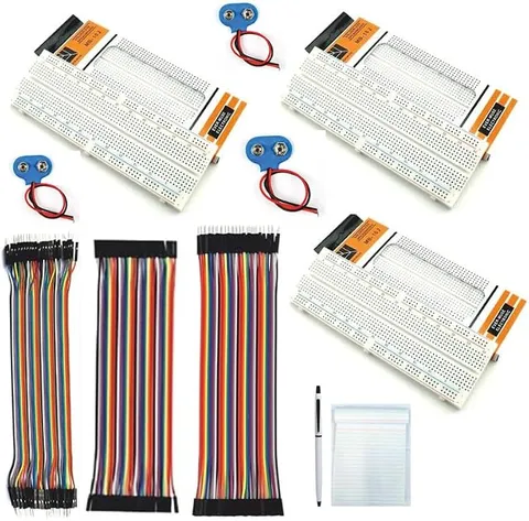
- Components and Spares
- Component
MB102 830 Tie Points 3 Solderless Breadboard
Code B0FGV2SXQC
- Paid for and delivered by Amazon. The current price and the delivery date for your PIN code are shown there.
- Sold by Gurukul Technicals Institute, Delhi.
- Need a different topic, a custom version or a school order? Ask on WhatsApp.
Component
About this part
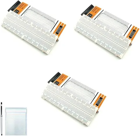
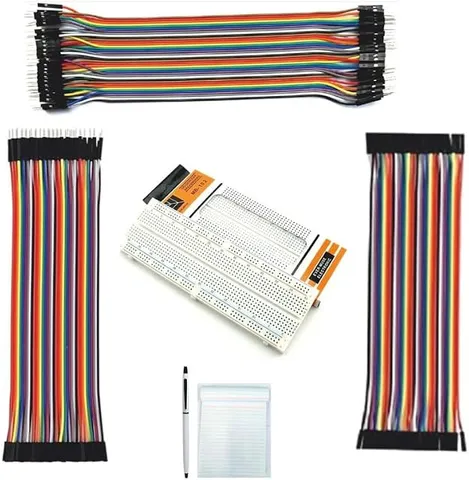
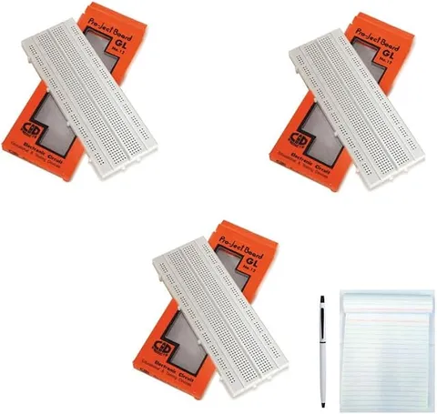
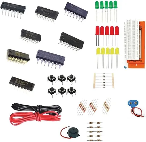
This economy pack is for building and testing circuits without soldering: the listing title mentions three MB102 830 tie-point solderless breadboards, jumper wires of male-male, male-female and female-female type (listed as 40M-M, M-F, F-F) and a clamp. A breadboard lets students try a circuit, fix mistakes and rebuild it in minutes, which makes it the first tool for any electronics or Arduino project.
What the listing says
- Economy Pack Electronic Components
How it works
The science behind it
The idea the part demonstrates, in words you can use in your report and when you explain it.
Under the holes of a breadboard are spring metal clips. In the main area, each short row of five holes is joined by one clip, so anything plugged into those five holes is electrically connected; in circuit terms they form one node at the same potential. The long strips along the edges are power rails, used for the positive supply and ground. The gap down the middle separates the two halves so that an IC can sit across it with each pin in its own row. An 830-point board is usually made up of 630 terminal points and 200 power rail points. Jumper wires complete the paths: male-male joins breadboard to breadboard, male-female joins a breadboard or Arduino header to a sensor module's pins, and female-female joins two pin headers. Popular school projects built on a breadboard include a 555 LED blinker, a clap switch, a rain alarm and Arduino sensor circuits.
Using it in your projects
Using solderless breadboards and jumper wires in your projects
What this part is good for, what else you need with it and how to connect it.
Projects you can build with it 7
- LEDs in series and parallel
- Transistor touch switch or night light
- 555 timer LED blinker
- Logic gate demonstration with push buttons and LEDs
- Traffic light project with a microcontroller
- Rain alarm or line-follower sensor test rig
- Trying out any circuit before soldering it on a board
What else you need 7
How to connect it 8 steps
- Look at the board
In the middle, each short row of five holes is joined underneath, and along the edges the long strips are the power rails.
Use the multimeter's continuity test to check whether each power rail runs the full length, because on some boards the rails are split in the middle.
Connect the battery's red wire to the rail marked plus and the black wire to the rail marked minus, using male-male jumpers.
Plug an LED into two different rows, and put a resistor from the row of its longer leg to the positive rail.
Join the row of the LED's shorter leg to the negative rail with a jumper: the LED should glow.
Add a push button in series and check that the LED now lights only while the button is pressed.
Use male-female jumpers to join sensor modules to a microcontroller board, and female-female jumpers to join two module pins directly.
Disconnect the battery before changing anything, and pull parts out gently by their bodies, not their legs.
Read this first
Safety first
Go through these points before you build or switch anything on. Younger students should do this with an adult.
- Breadboards are for low-voltage, low-current circuits only; never plug mains or a mains appliance into one.
- Never join the two power rails directly; a short circuit heats the battery and the wires.
- Do not run large motors through thin jumpers and the board; use a motor driver and separate, thicker wires.
- Keep small parts and jumpers away from younger children.
Troubleshooting
If something does not work
The usual problems with this part and how to fix them. Open a problem to see the fix.
The circuit works on one side of the board but not the other
The power rails are probably split in the middle. Add short jumpers to join the two halves of each rail.
The LED on the breadboard does not glow
Both legs may be in the same five-hole row, which shorts it out; move one leg to another row, and check the LED's direction.
A part keeps falling out
Its legs are bent or too thin. Straighten them, and avoid forcing very thick legs into the holes, which loosens the clips for everything after.
A jumper wire seems dead
The wire may be broken inside its insulation. Check it with the multimeter's continuity test and replace it.
Exhibition day
How to present it
A running order for the exhibition table or the practical, step by step.
Use red wires for positive and black for ground so the examiner can follow your circuit at a glance.
Check with a multimeter whether each power rail runs the full length; on some boards it is split in the middle.
Keep wires short and flat on the board so the circuit looks neat and is easy to debug.
Place ICs across the centre gap and explain why the gap is there.
Practice
Viva questions
Practice questions on this part, with short answers. Try each one aloud before you open the answer.
Why is a breadboard called solderless?
Because components and wires are pushed into spring clips, so circuits can be built and changed without soldering.
Which holes on a breadboard are connected together?
Each group of five holes in a row in the main area is connected, and each long power rail is connected along its length, or along each half on split-rail boards.
Why is there a gap in the middle of a breadboard?
So that a DIP IC can be placed across it, giving each pin its own separate row.
When would you use a male-to-female jumper wire?
To connect a breadboard or an Arduino header to a module that has male header pins, such as many sensor modules.
Buying checklist
Before you buy
What to check before you order the part, and what to do when it arrives.
1Before you order
- The title mentions three breadboards, jumper wires and a clamp; check the listing for how many wires of each type there are and what the clamp is for.
- Sort the jumpers by type (male-male, male-female, female-female) into a box straight away.
- Check the board size in the listing so it fits your project box or robot chassis.
- Check the delivery date for your PIN code on the marketplace, and order well before the exhibition or practical.
- Building it yourself: younger students should build with an adult, especially with motors, batteries and small parts.
2When it arrives
- When it arrives, check each board's rails with a multimeter and note any that are split.
Next steps
Take it further
Ways to turn this part into a bigger investigation or a stronger exhibition entry.
Practise reading a circuit diagram and laying it out neatly on the board with colour-coded wires.
Build and test a circuit on the breadboard, then move it onto a soldered perfboard.
Join two boards side by side for a larger microcontroller project.
Audience
Who it suits
Class 6 to 12 students, robotics and Arduino beginners, and engineering or diploma students prototyping circuits.
- CategoryComponents and Spares
- TypeComponent
Free to read
Free ebooks for this topic
Free PDF ebooks from Gurukul Technicals Institute on the science, the making and the presenting of projects like this one.
- Free PDF ebook
Electronic Components Handbook
Resistors, capacitors, LEDs, diodes, transistors and more, with how to use each
- Free PDF ebook
Your Science Exhibition Guide
Choose a project, build it, present it and answer the judges with confidence
- Free PDF ebook
Writing a Science Project File
How to write the report, from the cover page to the bibliography