- Components and Spares
- Component
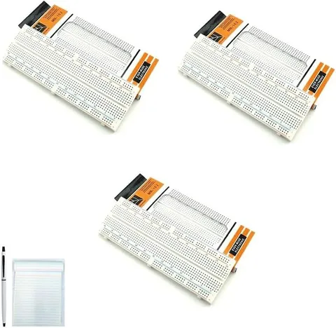
MB 102 830 Tie Points Solderless Breadboard
Code B0FGV36R82
- Paid for and delivered by Amazon. The current price and the delivery date for your PIN code are shown there.
- Sold by Gurukul Technicals Institute, Delhi.
- Need a different topic, a custom version or a school order? Ask on WhatsApp.
Component
About this part
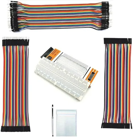
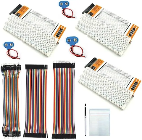
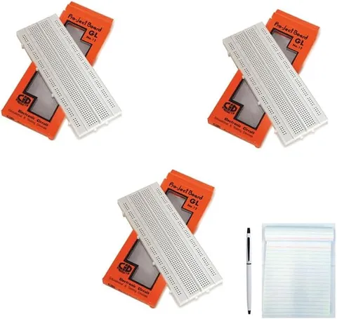
The MB-102 is a common solderless breadboard with 830 tie points, used to build and test circuits by simply pushing component legs and wires into its holes. Because nothing is soldered, a circuit can be changed or taken apart in seconds. The listing says this is a set of three, handy for building more than one project at a time.
What the listing says
- Value Saver
- Free Pen & Pad Electronic Components
How it works
The science behind it
The idea the part demonstrates, in words you can use in your report and when you explain it.
Under the plastic surface of a breadboard are strips of springy metal clips. Each clip joins a short row of five holes, so any leads pushed into the same row of five are electrically connected. On the standard MB-102 layout, 630 tie points sit in the central terminal area and 200 in the four long power rails along the edges, giving 830 in total. A channel runs down the middle so that an IC can sit across it, with each of its pins landing in a separate row. The holes are 2.54 mm apart, matching the spacing of IC pins. The power rails work like a home extension board, where every socket shares the same supply line. The main rule is continuity: current flows only through a closed path, and two leads placed in the same row are already joined, which is a common cause of short circuits.
Using it in your projects
Using a solderless breadboard in your projects
What this part is good for, what else you need with it and how to connect it.
Projects you can build with it 6
- Testing an LDR street light circuit before soldering it
- Building AND, OR and NOT gates with transistors or ICs
- A 555 timer LED flasher
- Trying a transistor amplifier or fire alarm circuit and changing resistor values
- Wiring sensors to a microcontroller board for a robotics project
- Comparing series and parallel LED circuits side by side
What else you need 7
How to connect it 8 steps
- Look at the board
The long lines marked + and − at the edges are the power rails, and each short row of five holes in the middle is joined underneath.
Use the multimeter's continuity mode to see which holes are connected, and check whether each power rail runs the full length of the board.
Connect the battery leads to one + rail and one − rail, red to +.
- Build a first test
A resistor from the + rail to a row, the LED's long leg in that same row, its short leg in another row, and a wire from that row back to the − rail.
Add a push button in the path and check that the LED lights only while the button is pressed.
Place any IC so that it straddles the centre channel, with each pin in its own row.
Keep wires short and flat, using red for positive and black for negative, so faults are easy to spot.
Disconnect the battery before moving parts, and use the other boards for other projects so a working circuit can stay as it is.
Read this first
Safety first
Go through these points before you build or switch anything on. Younger students should do this with an adult.
- Never join the + and − rails directly with a wire; the short circuit heats the wire and can damage the battery.
- Use only low-voltage batteries, up to 12 V; never mains power on a breadboard.
- Do not force thick legs into the holes, which spreads the spring clips; use thin wire or header pins.
- Keep small components away from young children.
Troubleshooting
If something does not work
The usual problems with this part and how to fix them. Open a problem to see the fix.
The LED does not light although everything looks right
Make sure the LED's two legs are not in the same row of five (that shorts it out), that it is the right way round, and that the power rail is not split in the middle.
The circuit works only when I press on a wire
The clip under that hole is loose, or the wire end is too thin or bent. Move it to another hole or strip a fresh end.
The battery gets warm
There is a short circuit. Disconnect at once and look for a wire or leg joining + and − directly.
A circuit with an IC behaves strangely
Check that the IC straddles the channel, that its notch faces the way your diagram shows, and that both power rails are fed if you use both sides of the board.
Exhibition day
How to present it
A running order for the exhibition table or the practical, step by step.
Explain with a quick sketch which holes are connected inside the board before you show your circuit.
Show on the board itself how the 830 tie points add up: 630 in the terminal area and 200 in the rails.
Show an IC straddling the centre channel and explain why it must sit that way.
Demonstrate how quickly a part can be swapped, which is why engineers prototype on breadboards first.
Practice
Viva questions
Practice questions on this part, with short answers. Try each one aloud before you open the answer.
What is a tie point on a breadboard?
A tie point is a hole where a component lead or wire can be inserted to make a connection.
Which holes on a breadboard are connected internally?
Each group of five holes in a terminal row is connected, and on most boards each power rail is connected along its length.
Why does an IC sit across the centre channel?
So that the pins on its two sides go into different rows and are not shorted together.
Why is a breadboard called solderless?
Parts are held by spring clips instead of solder, so circuits can be built, changed and reused easily.
Buying checklist
Before you buy
What to check before you order the part, and what to do when it arrives.
1Before you order
- Check the listing for the number of boards and tie points, and whether the boards can be joined side by side.
- Plan to get jumper wires separately if the listing does not mention them.
- Keep the sticky backing paper on until you decide where to fix a board.
- Store the boards flat and clean; dust in the holes causes poor contacts.
- Check the delivery date for your PIN code on the marketplace, and order well before the exhibition or practical.
- Check what is in the box on the marketplace listing, including any batteries or tools you need to add.
- Building it yourself: younger students should build with an adult, especially with motors, batteries and small parts.
2When it arrives
- Test the power rails with a multimeter as soon as the boards arrive.
Next steps
Take it further
Ways to turn this part into a bigger investigation or a stronger exhibition entry.
Build the same circuit on a breadboard and on a zero PCB, and compare build time and reliability in your report.
Use one board per stage (sensor, logic, output) and link them, the way engineers use modules.
Make a chart showing which holes connect inside the board, to help juniors in your class.
Audience
Who it suits
Suits Class 9 to 12 students, ITI, polytechnic and engineering learners, and anyone prototyping Arduino or electronics projects.
- CategoryComponents and Spares
- TypeComponent
Free to read
Free ebooks for this topic
Free PDF ebooks from Gurukul Technicals Institute on the science, the making and the presenting of projects like this one.
- Free PDF ebook
Electronic Components Handbook
Resistors, capacitors, LEDs, diodes, transistors and more, with how to use each
- Free PDF ebook
Your Science Exhibition Guide
Choose a project, build it, present it and answer the judges with confidence
- Free PDF ebook
Writing a Science Project File
How to write the report, from the cover page to the bibliography