- Physics
- Ready-made model
- Class 10 to 12
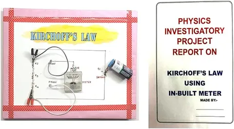
Kirchhoff’s Law KCL & KVL Physics Investigatory Project Working Model
Code B0G2TBMC8K
- Paid for and delivered by Amazon. The current price and the delivery date for your PIN code are shown there.
- Sold by Gurukul Technicals Institute, Delhi.
- Need a different topic, a custom version or a school order? Ask on WhatsApp.
In this project guide
Ready-made model
About this model
This investigatory model is about Kirchhoff's current law (KCL) and voltage law (KVL), the two rules used to solve any network of batteries and resistors. It helps a student show with real readings that current is conserved at a junction and that voltages balance around a closed loop.
How it works
The science behind it
The idea the model demonstrates, in words you can use in your report and when you explain it.
Kirchhoff's current law says that at any junction in a circuit, the total current entering equals the total current leaving. It follows from conservation of charge, since charge cannot pile up at a point. If 2 A enters a junction and 1.2 A leaves along one branch, the other branch must carry 0.8 A. Kirchhoff's voltage law says that around any closed loop, the algebraic sum of all emfs and potential drops is zero, which follows from conservation of energy. In a loop with a 9 V battery and two resistors, if one resistor drops 6 V, the other must drop 3 V. These laws solve circuits too complex for simple series and parallel rules, such as the Wheatstone bridge. The wiring in your home follows KCL: the current in the main line equals the sum of the currents drawn by every fan, light and appliance that is switched on.
Make it yourself
Make a Kirchhoff's laws circuit board yourself
Build your own version from scratch, or use the steps to understand how the ready-made model is put together before you present it.
What you need 9
Step by step 8 steps
Draw the circuit on the board: the battery feeds resistor R1 to junction A; from A, two branches through R2 and R3 meet again at junction B, which returns to the battery.
Fix test points at both junctions and at both ends of every resistor, and label each one.
Put a removable wire link in series in each of the three branches, so the multimeter can replace it to measure that branch's current.
Make the connections with screw terminals, or solder them with an adult, and check the wiring against your drawing.
Set the multimeter to DC volts and measure the battery voltage and the voltage across each resistor. Check that around each loop through the battery the drops across R1 and one branch resistor add up to the battery voltage, and that around the loop of R2 and R3 the two drops are equal and opposite, so they sum to zero.
Remove one link at a time and put the multimeter, on its milliampere range, in its place to read I1, I2 and I3. Check that I1 equals I2 + I3 at junction A.
Calculate the expected currents and voltages using Kirchhoff's laws and Ohm's law, and compare them with your readings.
Change one resistor and repeat, to show the laws still hold for a different circuit.
Read this first
Safety first
Go through these points before you build or switch anything on. Younger students should do this with an adult.
- Never connect the multimeter on a current range across the battery or across a resistor; it acts like a plain wire and can blow its fuse.
- Solder only with an adult, keep the hot iron on its stand, and work in a ventilated room.
- Use resistors of 1 kΩ or more so the currents stay at a few milliamperes and nothing gets hot.
- Disconnect the battery when you are not taking readings.
Troubleshooting
If something does not work
The usual problems with this model and how to fix them. Open a problem to see the fix.
The currents at the junction do not add up exactly
Small differences come from meter rounding, resistor tolerance and the battery voltage falling. A difference of a few percent is normal; use a fresh battery and take readings quickly.
The ammeter reads zero
The red probe may be in the volts socket instead of the milliampere socket, the meter's fuse may be blown, or the link was not removed. Check each in turn.
Some voltage readings come out negative
The probes are the other way round. Keep the sign and record it: in Kirchhoff's voltage law, signs matter, and a negative reading just means a drop in the other direction.
The battery voltage keeps falling while measuring
The battery is weak. Fit a fresh one and switch off between readings.
Exhibition day
How to present it
A running order for the exhibition table or the practical, step by step.
Mark every junction and loop on a circuit diagram chart and show the direction you chose for each current.
Take current and voltage readings with a multimeter and add them up in front of the examiner to show both laws hold.
State your sign convention clearly, for example that a drop across a resistor in the direction of current is taken as negative.
Expect small differences caused by meter error and wire resistance, and say so honestly.
Practice
Viva questions
Practice questions on this model, with short answers. Try each one aloud before you open the answer.
On which conservation law is KCL based?
KCL is based on the conservation of electric charge.
On which conservation law is KVL based?
KVL is based on the conservation of energy, since a charge that goes round a closed loop returns to the same potential.
Three wires meet at a junction and 3 A and 2 A flow in through two of them. What flows through the third?
5 A flows out through the third wire, because the total current entering a junction equals the total current leaving it.
Name one circuit that is analysed using Kirchhoff's laws.
The Wheatstone bridge; its balance condition P/Q = R/S is derived using KCL and KVL.
Project file
Project file outline
The headings of the project file, in order. Give each heading its own section and write it in your own words.
Free ebook: Writing a Science Project FileContents
- Aim: to verify Kirchhoff's current law and voltage law
- Theory: conservation of charge and of energy in a circuit
- Sign conventions for currents and potential drops
- Circuit diagram and component values
- Procedure for measuring branch currents and voltages
- Observation tables for the current law and the voltage law
- Calculations: theoretical values compared with measured values
- Sources of error and precautions
- Conclusion and uses, such as solving networks and the Wheatstone bridge
Buying checklist
Before you buy
What to check before you order the model, and what to do when it arrives.
1Before you order
- Check that Kirchhoff's laws are in your syllabus or approved by your teacher as an investigatory project.
- Read the listing to see what is mentioned with the model; you will almost certainly need your own multimeter for readings.
- Check that the resistor values are readable or marked, since your calculations depend on them.
- Keep the box to protect the board and terminals on the way to school.
- Check the delivery date for your PIN code on the marketplace, and order well before the exhibition or practical.
- Practise explaining it. Judges ask what the model shows and why; knowing the science matters as much as the model. The viva questions above are a good place to start.
2When it arrives
- Test it with a multimeter soon after it arrives and note the readings you get, so you know what to expect on the day.
Next steps
Take it further
Ways to turn this model into a bigger investigation or a stronger exhibition entry.
Add a second source in one branch and solve the network with simultaneous equations, then check with readings.
Build a Wheatstone bridge on the same board and show the balance condition with your multimeter.
Model the same circuit in free circuit-simulation software and compare its values with your measurements.
Audience
Who it suits
Suits Class 12 physics investigatory projects on current electricity and first-year diploma or engineering circuit labs.
- ClassClass 10 to 12
- SubjectPhysics
- TypeReady-made model
Free to read
Free ebooks for this topic
Free PDF ebooks from Gurukul Technicals Institute on the science, the making and the presenting of projects like this one.
- Free PDF ebook
Physics Working Models Explained
Twenty classic models, how each works and how to make it
- Free PDF ebook
Investigatory Projects for Class 11 and 12
Topics, method and report structure for physics, chemistry and biology
- Free PDF ebook
Your Science Exhibition Guide
Choose a project, build it, present it and answer the judges with confidence
- Free PDF ebook
Writing a Science Project File
How to write the report, from the cover page to the bibliography