- Physics
- Ready-made model
DC Inductive
Code B0G2T9B5XD
- Paid for and delivered by Amazon. The current price and the delivery date for your PIN code are shown there.
- Sold by Gurukul Technicals Institute, Delhi.
- Need a different topic, a custom version or a school order? Ask on WhatsApp.
In this project guide
Ready-made model
About this model
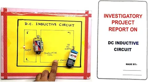
This physics project is about electromagnetic induction in a DC circuit containing an inductor and a resistor, known as an RL circuit. It helps a student explain self-induction, the gradual rise and fall of current in a coil, and why sparks can appear when an inductive circuit is switched off.
What the listing says
- Electromagnetic Induction & RL Circuit Project Educational Electronic Hobby Kit
How it works
The science behind it
The idea the model demonstrates, in words you can use in your report and when you explain it.
When the current in a coil changes, the magnetic flux linked with the coil changes, and by Faraday's law an emf is induced in the coil itself. This is self-induction. By Lenz's law the induced emf always opposes the change that causes it: e = −L (dI/dt), where L is the inductance, measured in henry (H). In an RL circuit connected to a battery, the current therefore does not jump to its final value V ÷ R at once. It grows gradually, reaching about 63% of its final value after one time constant, τ = L ÷ R; for L = 0.5 H and R = 10 Ω, τ = 0.05 s. When the circuit is broken suddenly, the current falls very fast and a large emf is induced, which can cause a spark across the switch. The choke in an older tube light uses this sudden emf to help start the tube.
Make it yourself
Make an RL circuit self-induction model yourself
Build your own version from scratch, or use the steps to understand how the ready-made model is put together before you present it.
What you need 10
Step by step 9 steps
Wind several hundred turns of enamelled wire neatly round the iron core, leaving 15 cm free at each end, and sand the enamel off the last 1 cm of each end.
Measure the coil's resistance with the multimeter and set the rheostat, or choose resistors, to the same value.
Build two branches in parallel across the push button and cells: branch A is one bulb in series with the coil, branch B is the other bulb in series with the rheostat.
Press the button and watch both bulbs closely: the bulb with the rheostat lights at once, while the bulb with the coil comes up a moment later, because the coil's induced emf opposes the rising current. The delay is short, so watch them side by side.
For the switch-off test, remove branch B and connect the coil alone in series with the button and cells, with the neon lamp connected across the coil's two ends.
Press the button for a second and release it: the neon flashes at the instant of release, showing that a voltage far higher than 6 V was induced as the current collapsed.
Connect the diode across the coil with its band towards the cells' positive side and repeat: the flash disappears, because the diode gives the collapsing current a safe path. This is why relays and motor circuits carry such a diode.
Pull the iron core out and repeat both tests: the delay and the flash both become weaker, because the coil's inductance is much smaller without iron.
Label the board with the circuit diagrams, e = −L (dI/dt) and the time constant τ = L ÷ R.
Read this first
Safety first
Go through these points before you build or switch anything on. Younger students should do this with an adult.
- Keep your fingers off the coil ends and the neon lamp leads when the button is released; the induced voltage can give a sharp sting even from 6 V cells.
- In the switch-off test press the button for only a second or two at a time, because the coil alone lets a large current flow and the cells and wire can get warm.
- Use only cells for this model; never connect it to the mains or to a mains choke wired to a supply.
- Use sandpaper and any soldering iron carefully, and the iron only with an adult.
Troubleshooting
If something does not work
The usual problems with this model and how to fix them. Open a problem to see the fix.
Both bulbs seem to light at the same time
The coil's inductance is too small for the delay to show, or the rheostat is not matched. Add more turns, pack the core tightly or bend the rods into a closed loop, and set the rheostat so both bulbs end up equally bright. The switch-off flash is the more reliable part of this model.
The bulb in the coil branch never lights fully
The coil's resistance is much higher than the rheostat's, or the enamel was not cleaned off the wire ends. Re-sand the ends and measure the resistance again.
The neon lamp does not flash
Branch B may still be connected, giving the current another path, or the cells are weak. Remove branch B, use fresh cells, and release the button sharply.
The cells run down quickly
The bare coil is almost a short circuit for the cells. Keep presses short, or put a small resistor in series with the coil for the switch-off test.
Exhibition day
How to present it
A running order for the exhibition table or the practical, step by step.
Draw the graphs of current against time for switching on and switching off, and mark the time constant on them.
Explain Lenz's law with the idea that a coil resists any change in current, just as inertia resists a change in motion.
Write τ = L ÷ R on a chart with a worked example, and explain what a larger inductance would do.
Mention that large coils can produce high voltages when switched off, which is why protective diodes are placed across relay and motor coils.
Practice
Viva questions
Practice questions on this model, with short answers. Try each one aloud before you open the answer.
What is meant by the self-induction of a coil?
Self-induction is the production of an emf in a coil when the current through that same coil changes.
What is the time constant of an RL circuit?
It is τ = L ÷ R, the time in which the current rises to about 63% of its final value after switching on.
What is the SI unit of inductance?
The henry (H); a coil has an inductance of 1 H if a current changing at 1 A per second induces an emf of 1 V in it.
Why can a spark appear at the switch when an inductive circuit is turned off?
The current falls very quickly, so a large emf is induced in the coil, which can make the current jump across the opening switch as a spark.
Project file
Project file outline
The headings of the project file, in order. Give each heading its own section and write it in your own words.
Free ebook: Writing a Science Project FileContents
- Aim: to study self-induction in a DC circuit containing an inductor and a resistor
- Introduction: magnetic flux, Faraday's law and Lenz's law
- Self-inductance and its unit, the henry
- Growth and decay of current in an RL circuit, and the time constant τ = L ÷ R
- Construction: winding the coil and building the two-bulb board
- Observations: switch-on delay, switch-off flash, effect of the diode and of removing the iron core
- Applications and problems: sparks at switches, protection diodes, chokes and ignition coils
- Precautions and conclusion
- Bibliography
Buying checklist
Before you buy
What to check before you order the model, and what to do when it arrives.
1Before you order
- Check that electromagnetic induction is in your syllabus; it is usually a Class 12 topic, even though this model is listed for younger classes, so ask your teacher what level they expect.
- Read the listing to see how the model shows induction and what power source it uses, so you can arrange cells.
- Practise explaining Lenz's law with the switch-off flash as your example.
- Keep spare cells and the box for transport.
- Check the delivery date for your PIN code on the marketplace, and order well before the exhibition or practical.
2When it arrives
- Test it on arrival and repeat the demonstration several times, since the effects are quick and need practice to show clearly.
Next steps
Take it further
Ways to turn this model into a bigger investigation or a stronger exhibition entry.
With a teacher, view the rise of current on a school oscilloscope and estimate the time constant from the trace.
Wind coils with different numbers of turns on the same core and compare how strongly each shows the effect.
Explain how a car's ignition coil uses the same switch-off effect to make the spark for the engine.
Audience
Who it suits
Suits Class 12 physics investigatory projects on electromagnetic induction and diploma students studying inductors.
- SubjectPhysics
- TypeReady-made model
Free to read
Free ebooks for this topic
Free PDF ebooks from Gurukul Technicals Institute on the science, the making and the presenting of projects like this one.
- Free PDF ebook
Electricity and Magnetism Experiments
Hands-on experiments with cells, wires, bulbs and magnets
- Free PDF ebook
Physics Working Models Explained
Twenty classic models, how each works and how to make it
- Free PDF ebook
Your Science Exhibition Guide
Choose a project, build it, present it and answer the judges with confidence
- Free PDF ebook
Writing a Science Project File
How to write the report, from the cover page to the bibliography