- Physics
- Ready-made model
- Class 10 to 12
Automatic Night Lamp and Fan Using IC 555 Physics Investigatory Minor Project and Model
Code B0C3H32V3M
- Paid for and delivered by Amazon. The current price and the delivery date for your PIN code are shown there.
- Sold by Gurukul Technicals Institute, Delhi.
- Need a different topic, a custom version or a school order? Ask on WhatsApp.
In this project guide
Ready-made model
About this model
A physics minor project built around the IC 555 timer that switches a night lamp and a fan automatically instead of by hand. It shows how a sensor and a timer chip together can make a simple smart-home device.
How it works
The science behind it
The idea the model demonstrates, in words you can use in your report and when you explain it.
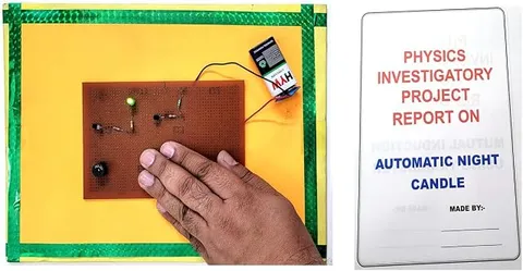
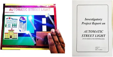
The 555 timer IC contains two comparators, a flip-flop and a discharge transistor. One comparator watches the trigger pin and the other the threshold pin, comparing them with one-third and two-thirds of the supply voltage. When the trigger voltage drops below one-third of the supply, the flip-flop sets and the output goes high. In a typical automatic night lamp, a light dependent resistor (LDR) and a fixed resistor form a voltage divider. An LDR has low resistance in light and high resistance in darkness, so as daylight fades the divider voltage crosses the comparator's level, the 555 output switches, and a transistor or relay turns the lamp on. The same output, or a second sensing stage, can switch a small fan. With the trigger and threshold pins tied together, the gap between the two levels stops the lamp flickering at dusk. Street lights that switch on by themselves at sunset use the same idea.
Make it yourself
Make an automatic night lamp and fan with a 555 timer yourself
Build your own version from scratch, or use the steps to understand how the ready-made model is put together before you present it.
What you need 9
Step by step 8 steps
Solder the 555 socket. Connect pins 8 and 4 to positive, pin 1 to negative, and the 10 nF capacitor from pin 5 to negative.
Join pins 2 and 6. Connect the LDR from positive to this junction, and the preset from the junction to negative.
Connect each white LED with its 470 Ω resistor from pin 3 to negative, long leg towards pin 3.
For the fan, connect pin 3 through the 1 kΩ resistor to the transistor's base, the emitter to negative, and the fan between positive and the collector. Fit the diode across the fan with its band towards positive.
Fit the IC and switch on in normal room light: the lamp and fan should stay off. If they do not, turn the preset.
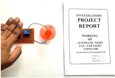
Cover the LDR with your hand or a cup: the lamp and fan switch on. Uncover it and they switch off.
Adjust the preset so they switch on at about dusk. The 555 switches on below one-third of the supply voltage and off above two-thirds, so the light level for 'on' is darker than the level for 'off', which stops flickering at twilight.
Mount the LDR on the outside wall of the model house facing outwards, away from the lamp's own light, with the lamp on the ceiling and the fan on a wall inside.
Read this first
Safety first
Go through these points before you build or switch anything on. Younger students should do this with an adult.
- Use only a battery pack of up to 12 V, and never connect this circuit to a household lamp or ceiling fan.
- Keep the diode across the fan; without it, the motor's voltage spike when it switches off can damage the transistor.
- Solder only with an adult present, and fit the IC with its notch the right way round.
- Keep fingers away from the fan blade when the lamp and fan switch on suddenly during testing.
Troubleshooting
If something does not work
The usual problems with this model and how to fix them. Open a problem to see the fix.
The lamp blinks on and off by itself once it gets dark
The LDR can see the lamp's own light, so it switches itself off again. Point the LDR away from the lamp or put it in a short black tube.
The lamp is always on or always off
Turn the preset slowly through its range. Also check that pins 2 and 6 are joined and that the LDR goes to positive, not negative.
The LEDs light but the fan does not run
Check the transistor's legs and the diode's direction: a reversed diode short-circuits the fan. A weak battery may also light LEDs but not start a motor.
The 555 gets hot
It may be in backwards, or the fan may have been connected straight to pin 3. Always drive the fan through the transistor.
Exhibition day
How to present it
A running order for the exhibition table or the practical, step by step.
Cover the light sensor with your hand to show the lamp switching on, then uncover it to switch it off.
Find out from your circuit what controls the fan, whether light, temperature or a timer, and explain it clearly.
Show the 555 pin diagram on a chart and point to the trigger, threshold and output pins.
If a relay is used, explain why: it lets a small control circuit switch a separate, larger load safely.
Practice
Viva questions
Practice questions on this model, with short answers. Try each one aloud before you open the answer.
What is inside a 555 timer IC?
It contains two comparators, a flip-flop, a discharge transistor and a resistor divider that sets reference levels at one-third and two-thirds of the supply.
How does an LDR sense darkness?
Its resistance rises sharply in darkness, which changes the voltage of the divider connected to the 555.
When does the 555 output go high?
In the usual configuration, the output goes high when the trigger pin voltage falls below one-third of the supply voltage.
Why is a relay or transistor used to drive the lamp?
The 555 output can supply only limited current, so a transistor or relay switches the larger current that the lamp or fan needs.
Project file
Project file outline
The headings of the project file, in order. Give each heading its own section and write it in your own words.
Free ebook: Writing a Science Project FileContents
- Aim: to switch a lamp and a fan on automatically when it gets dark, using an LDR and a 555 timer
- Introduction: automatic street lights and saving energy
- Working of the LDR and the voltage divider
- Inside the 555: two comparators at one-third and two-thirds of the supply, a flip-flop and the output stage
- The 555 as a Schmitt trigger, and why its two switching levels stop flicker at dusk
- Circuit diagram: LDR input, LED lamp and transistor fan driver
- Observations: light levels at which the lamp switches on and off
- Applications and improvements: street lights, garden lights and a fan controlled by temperature
- Conclusion and bibliography
Buying checklist
Before you buy
What to check before you order the model, and what to do when it arrives.
1Before you order
- Check that a 555 or sensor project suits your class level and your teacher's instructions.
- Read the listing to see what battery or power source the model needs.
- Exhibition halls are bright, so keep a small cup or cover ready to put over the sensor and show the lamp switching on.
- Check the delivery date for your PIN code on the marketplace, and order well before the exhibition or practical.
- Practise explaining it. Judges ask what the model shows and why; knowing the science matters as much as the model. The viva questions above are a good place to start.
2When it arrives
- Test it as soon as it arrives and keep the box for transport.
Next steps
Take it further
Ways to turn this model into a bigger investigation or a stronger exhibition entry.
Add a second 555 with a thermistor so the fan switches on when the room is warm, while the lamp still follows the light level.
Measure the LDR's resistance in different light levels with a multimeter and plot a graph.
Use a relay module to switch a separate 12 V lamp, and explain why real street-light switching gear is installed by electricians.
Audience
Who it suits
Suits Class 10 to 12 physics investigatory projects and diploma students doing minor electronics projects.
- ClassClass 10 to 12
- SubjectPhysics
- TypeReady-made model
Free to read
Free ebooks for this topic
Free PDF ebooks from Gurukul Technicals Institute on the science, the making and the presenting of projects like this one.
- Free PDF ebook
Physics Working Models Explained
Twenty classic models, how each works and how to make it
- Free PDF ebook
Investigatory Projects for Class 11 and 12
Topics, method and report structure for physics, chemistry and biology
- Free PDF ebook
Your Science Exhibition Guide
Choose a project, build it, present it and answer the judges with confidence