- Physics
- Ready-made model
- Class 10 to 12
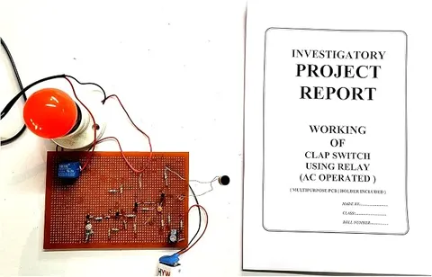
Clap Switch Using Relay Physics Investigatory Minor Project and Model
Code B0C3H3SH68
- Paid for and delivered by Amazon. The current price and the delivery date for your PIN code are shown there.
- Sold by Gurukul Technicals Institute, Delhi.
- Need a different topic, a custom version or a school order? Ask on WhatsApp.
In this project guide
Ready-made model
About this model
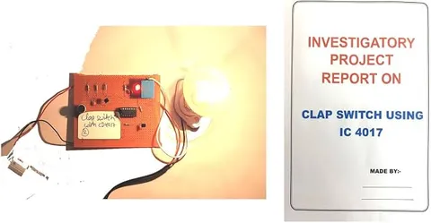
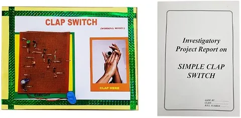
This clap switch turns a device on or off when you clap your hands, and uses a relay to do the actual switching. It shows how a sound can be turned into an electrical signal that controls a separate circuit.
How it works
The science behind it
The idea the model demonstrates, in words you can use in your report and when you explain it.
A clap is a short, sharp sound wave. A microphone converts it into a small electrical signal, and a transistor amplifier makes that signal strong enough to trigger the control stage. The control stage usually works as a flip-flop, so each clap changes its state: one clap switches the load on and the next switches it off. Its output drives a relay. A relay is an electrically operated switch: current through its coil creates an electromagnet, which pulls a metal armature and moves a set of contacts, closing a normally open (NO) contact or opening a normally closed (NC) one. Because the coil circuit and the contact circuit are separate, a small low-voltage current can control a larger current in another circuit while keeping the two electrically isolated. A diode is usually placed across the coil to protect the transistor from the voltage spike produced when the coil switches off. The click you hear is the armature moving.
Make it yourself
Make a clap switch with a relay yourself
Build your own version from scratch, or use the steps to understand how the ready-made model is put together before you present it.
What you need 9
Step by step 8 steps
Build the microphone and the two-transistor amplifier so a sharp clap gives a strong pulse at the second transistor's collector, and check it with a test LED.
Feed that pulse to the clock pin of the CD4017, tie its enable pin to negative, and join its Q2 output to its reset pin, so each clap toggles Q1 between HIGH and LOW.
Connect Q1 through the 10 kΩ resistor to the driver transistor's base, and the relay coil between the positive rail and the driver's collector.
Fit the 1N4007 across the relay coil with its band towards positive; it absorbs the voltage spike when the coil switches off.
Wire the 6 V pack and the bulb through the relay's common and normally open (NO) contacts, and the LED with its resistor through the normally closed (NC) contact.
- Switch on
The LED is lit and the bulb is off. Clap once and the relay clicks, the bulb comes on and the LED goes off; clap again to swap back.
Use the multimeter to show that no wire joins the bulb circuit to the clap circuit; the relay links them only through its magnet.
Measure the current in the relay coil and in the bulb, and explain how a small current in one circuit controls a larger current in another.
Read this first
Safety first
Go through these points before you build or switch anything on. Younger students should do this with an adult.
- Even if the relay's label shows a mains rating, students use it only with cells; never connect a relay project to mains wiring or appliances.
- Always fit the diode across the relay coil, or the switching spike can destroy the driver transistor.
- Keep the two battery circuits separate, using only the 9 V battery and the 6 V pack.
- Solder only with an adult, and touch a grounded metal object before handling the CD4017.
Troubleshooting
If something does not work
The usual problems with this model and how to fix them. Open a problem to see the fix.
The relay clicks but the bulb does not light
The bulb is on the wrong contact or its own cells are flat. Use the multimeter's continuity test to find the common and NO pins, and check the 6 V pack.
The relay chatters or buzzes
The coil is not getting a steady current, often because the 9 V battery is weak or the driver transistor is not fully on. Fit a fresh battery and check the base resistor.
One clap switches it on and straight off
The clap's echo is being counted as a second clap. Make the amplifier less sensitive, or add a short delay stage such as a 555 monostable before the counter.
Nothing happens when I clap
Test the amplifier with an LED first, then check that the CD4017 has power and that its enable pin is tied to negative.
Exhibition day
How to present it
A running order for the exhibition table or the practical, step by step.
Clap once to switch on and again to switch off, and let the audience hear the relay click.
Explain the job of each stage in turn: microphone, amplifier, flip-flop and relay.
Mention that a loud bang nearby can also trigger it, and explain why.
If you connect any appliance to the relay, do it only with a teacher's help, because mains wiring is dangerous.
Practice
Viva questions
Practice questions on this model, with short answers. Try each one aloud before you open the answer.
What is a relay?
An electrically operated switch in which an electromagnet moves a set of contacts.
What do NO and NC mean on a relay?
Normally open and normally closed, which describe the state of the contacts when no current flows through the coil.
What does the microphone do in a clap switch?
It converts the sound of the clap into an electrical signal.
Why is a relay used instead of switching the load directly with the transistor?
A relay can switch a larger current or a different voltage, and it keeps the control circuit electrically isolated from the load.
Project file
Project file outline
The headings of the project file, in order. Give each heading its own section and write it in your own words.
Free ebook: Writing a Science Project FileContents
- Aim: to switch a separate circuit on and off by clapping, using a relay
- From sound to signal: the microphone and the transistor amplifier
- The CD4017 counter used as an on/off toggle
- The relay: coil, armature, and normally open and normally closed contacts
- Why the relay coil needs a protection diode
- Circuit diagram showing the two separate circuits
- Observations: currents measured in the control and switched circuits
- Uses of relays in homes, cars and industry, and conclusion
Buying checklist
Before you buy
What to check before you order the model, and what to do when it arrives.
1Before you order
- The title calls it a minor project; check with your teacher that it suits your class and syllabus.
- Read the listing to see what the relay is shown switching and what supply it needs; do not assume batteries or a lamp are included.
- Whatever the relay's rating, use it only with low-voltage battery loads at school.
- Keep the box so the relay and microphone are not knocked loose in transport.
- Check the delivery date for your PIN code on the marketplace, and order well before the exhibition or practical.
- Practise explaining it. Judges ask what the model shows and why; knowing the science matters as much as the model. The viva questions above are a good place to start.
2When it arrives
- When it arrives, test it in a quiet room and a noisy one a few days before the exhibition.
Next steps
Take it further
Ways to turn this model into a bigger investigation or a stronger exhibition entry.
Add a 555 monostable so the light switches itself off after a set time, like a corridor light.
Use a relay with two changeover contacts, wired so each clap reverses a small DC motor, and explain the wiring.
Find the lowest coil voltage at which the relay pulls in and the voltage at which it drops out, and discuss why they differ.
Audience
Who it suits
Class 9 to 12 students and electronics hobbyists making a home-automation style project.
- ClassClass 10 to 12
- SubjectPhysics
- TypeReady-made model
Free to read
Free ebooks for this topic
Free PDF ebooks from Gurukul Technicals Institute on the science, the making and the presenting of projects like this one.
- Free PDF ebook
Electricity and Magnetism Experiments
Hands-on experiments with cells, wires, bulbs and magnets
- Free PDF ebook
Physics Working Models Explained
Twenty classic models, how each works and how to make it
- Free PDF ebook
Investigatory Projects for Class 11 and 12
Topics, method and report structure for physics, chemistry and biology
- Free PDF ebook
Your Science Exhibition Guide
Choose a project, build it, present it and answer the judges with confidence