PHYSICS PROJECT REPORT ON VERNIER CLIPPER
A close-up of a caliper’s measurement scales. Assuming the caliper has no “zero error” (that is, it registers 0.00 mm when fully closed) the image shows a reading of 3.58 mm ± 0.02 mm. This is found by adding 3.00 mm (left red mark) read off from the fixed main (upper) scale to 0.58 mm (right red mark) obtained from the sliding vernier (lower) scale. The main scale reading is determined by the rightmost tick on the main scale that is to the left of the zero tick on the vernier scale. The vernier reading is found by locating the closest aligned lines between the two scales. The 0.02 mm inscription indicates the caliper’s precision and is just the width that corresponds to the smallest interval on the vernier scale.
A vernier scale is a visual aid that allows the user to measure more precisely than could be done unaided when reading a uniformly divided straight or circular measurement scale. It is a subsidiary scale that indicates where the measurement lies in between two of the graduations on the main scale. Verniers are common on sextants used in navigation, scientific instruments used to conduct experiments, machinists‘ (or jewelers‘) measuring tools (all sorts, but especially calipers and micrometers) used to work materials to fine tolerances, on theodolites used in surveying, and in absolute encoders to measure linear or rotational displacements.
Contents
History[edit]
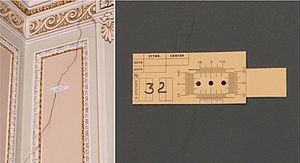
Mechanical displacement gauges with vernier scales on wall cracks (Moika Palace, Saint Petersburg).
Calipers without a vernier scale originated in ancient China as early as the Qin dynasty (AD 9) The secondary scale, which contributed extra precision, was invented in 1631 by French mathematician Pierre Vernier (1580–1637). Its use was described in detail in English in Navigatio Britannica (1750) by mathematician and historian John Barrow. While calipers are the most typical use of Vernier scales today, they were originally developed for angle-measuring instruments such as astronomical quadrants.
In some languages, the Vernier scale is called a nonius, a precursor to the Vernier scale developed by Portuguesemathematician, cosmographer Pedro Nunes (1502–1578), latinised as Petrus Nonius. It was known by this name in English until the end of the 18th century
The name “vernier” was popularised by the French astronomer Jérôme Lalande (1732–1807) through his Traité d’astronomie (2 vols) (1764)
Construction
In the following, N is the number of divisions the maker wishes to show at a finer level of measure.
Direct verniers are the most common. The indicating scale is constructed so that when its zero point coincides with the start of the data scale, its graduations are at a slightly smaller spacing than those on the data scale and so none but the last graduation coincide with any graduations on the data scale. N graduations of the indicating scale cover N−1 graduations of the data scale.
Retrograde verniers are found on some devices, including surveying instruments.A retrograde vernier is similar to the direct vernier, except its graduations are at a slightly larger spacing than on the main scale. N graduations of the indicating scale cover N+1 graduations of the data scale. The retrograde vernier also extends backwards along the data scale.
Direct and retrograde verniers are read in the same manner.
Use
The main use of the vernier caliper is to measure the internal and the external diameters of an object. To measure using a vernier scale, the user first reads the finely marked “fixed” scale (i.e. the main scale; see the diagram). This measure is typically between two of the main scale’s smallest graduations. The user then reads the vernier scale (see diagram), which measures between the smallest graduations on the fixed scale—providing much greater precision.
Least count
The difference between the value of one main scale division and the value of one Vernier scale division is known as least count of the Vernier. It is also known as Vernier constant. Let the measure of the smallest main scale reading, that is the distance between two consecutive graduations (also called its pitch) be S and the distance between two consecutive Vernier scale graduations be V such that the length of (n-1) main scale divisions is equal to n Vernier scale divisions. Then,
the length of (n-1) main scale divisions = the length of n vernier scale division
or, (n-1)S = nV
or, nS-S = nV
or, S = nS – nV
or, S/n = (S-V)
or (Pitch)/(Number of Vernier scale divisions) = (Length of one main scale division – Length of one Vernier scale division)
S/n and (S-V) are both equal to the least count of vernier scale, and are also called the vernier constant.
Examples
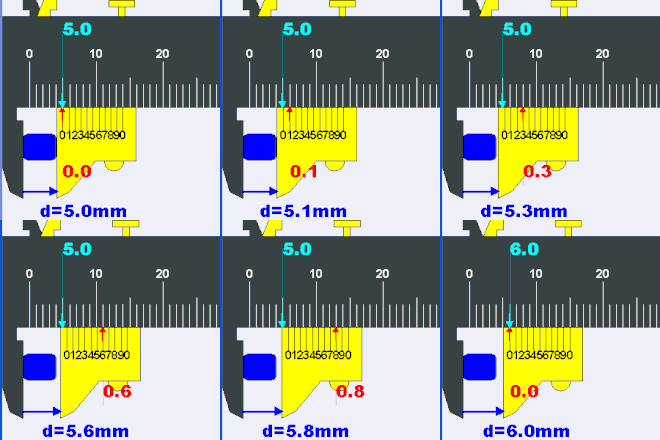
On decimal measuring instruments, as in the diagram below, the indicating scale has 10 graduations that cover the same length as 9 on the data scale. Note that the vernier’s 10th graduation is omitted.
On an angular measurement instrument, the data scale might be in half-degrees, with an indicator scale that provides 30 1-minute graduations (that span 29 of the half-degree graduations).
Mechanism of a vernier scale
The vernier scale is constructed so that it is spaced at a constant fraction of the fixed main scale. So for a decimal measuring device each mark on the vernier is spaced nine tenths of those on the main scale. If you put the two scales together with zero points aligned, the first mark on the vernier scale is one tenth short of the first main scale mark, the second two tenths short, and so on up to the ninth mark—which is misaligned by nine tenths. Only when a full ten marks are counted is there alignment, because the tenth mark is ten tenths—a whole main scale unit short, and therefore aligns with the ninth mark on the main scale.
Now if you move the vernier by a small amount, say, one tenth of its fixed main scale, the only pair of marks that come into alignment are the first pair, since these were the only ones originally misaligned by one tenth. If we move it two tenths, the second pair aligns, since these are the only ones originally misaligned by that amount. If we move it five tenths, the fifth pair aligns—and so on. For any movement, only one pair of marks aligns and that pair shows the value between the marks on the fixed scale.
Vernier acuity
Vernier scales work so well because most people are especially good at detecting which of the lines is aligned and misaligned, and that ability gets better with practice, in fact far exceeding the optical capability of the eye. This ability to detect alignment is called ‘Vernier acuity’ Historically, none of the alternative technologies exploited this or any other hyperacuity, giving the Vernier scale an advantage over its competitors.
Zero error
Zero error is defined as the condition where a measuring instrument registers a reading when there should not be any reading. In case of vernier calipers it occurs when a zero on main scale does not coincide with a zero on vernier scale. The zero error may be of two types i.e. when the scale is towards numbers greater than zero it is positive else negative. The method to use a vernier scale or caliper with zero error is to use the formula: actual reading = main scale + vernier scale − (zero error). Zero error may arise due to knocks that cause the calibration to be thrown off at the 0.00 mm when the jaws are perfectly closed or just touching each other.
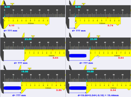
When the jaws are closed and if the reading is 0.10mm, the zero error is referred to as +0.10mm. The method to use a vernier scale or caliper with zero error is to use the formula ‘actual reading = main scale + vernier scale − (zero error)’ thus the actual reading is 19.00 + 0.54 − (0.10) = 19.44 mm
Positive zero error refers to the case when the jaws of the vernier caliper are just closed and the reading is a positive reading away from the actual reading of 0.00mm. If the reading is 0.10mm, the zero error is referred to as +0.10 mm.
When the jaws are closed and if the reading is −0.08mm, the zero error is referred to as +0.08 mm. The method to use a vernier scale or caliper with zero error is to use the formula ‘actual reading = main scale + vernier scale + (zero error)’ thus the actual reading is 19.00 + 0.36 + (+0.08) = 19.44 mm
Negative zero error refers to the case when the jaws of the vernier caliper are just closed and the reading is a negative reading away from the actual reading of 0.00mm. If the reading is 0.08mm, the zero error is referred to as +0.08mm. If positive, the error is subtracted from the mean reading the instrument reads. Thus if the instrument reads 4.39 cm and the error is +0.05, the actual length will be 4.39-0.05=4.34 cm. If negative, the error is added to the mean reading the instrument reads. Thus if the instrument reads 4.39 cm and as above the error is -0.05 cm, the actual length will be 4.39+0.05=4.44 cm. (Considering that, the quantity is called zero correction which should always be added algebraically to the observed reading to the correct value.)
Zero Error (Z.E) = + or- n* Least Count(L.C).
LOOKING FOR A WORKING MODEL FOR SCHOOL OR COLLEGE?
12th class is a no risk class. It is the class which decide your future. Whether you are going to work in MNC or going to work with usual private firms, it all depends here. To ensure the good marks to students we always stands behind them with all practical and theoretical support on Physics investigatory project. These Physics investigatory projects are usually have to be made by all students with physics and to be shown in boards practical. We at Gurukul Technicals Institute provide every student the theory behind the projects and give all possible required material to make the project work successfully. We duly provide equipped lab with latest lab materials. Conductors and Semiconductors are provided with Circuit diagram so that student can make project easily. Students make projects such as Full wave rectifier, Half wave rectifier, Fire alarm, rain alarm, Electromagnetic Induction, Logic gates(AND gate, OR gate, NOT gate, XAND gate, XNOR gate), Transistor as switch, Transistor as amplifier, Charging and Discharging of Capacitors, Series and Parallel Resistance etc etc. Students also get help on making these above given projects to made on cardboard or on breadboard as instructed by teacher. Students are also welcome to take help on report on given physics investigatory projects. After reading this website you can also send this information to your friend or relative studying in 12th class so it will make useful to him/her.
Get Readymade Project anywhere in India on just a Click away! That too with Report!
Prompt Delivery! COD Available! All over India Delivery! Order Now!!
CLICK HERE TO VIEW ALL 12th CLASS INVESTIGATORY PROJECT WITH REPORT LISTED ON AMAZON.IN WEBSITE
CLICK HERE TO VIEW MINOR,MAJOR AND ALL OTHER INVESTIGATORY PROJECTS ON FLIPKART.COM WEBSITE
Physics Projects with Reports:
- TO CONSTRUCT A CIRCUIT FOR TOUCH ALARM.
- EDDY CURRENT {WITHOUT MODEL }
- PHOTOCONDUCTIVE CELL
- MUTUAL INDUCTION
- TO STUDY NPN-TRANSISTOR AMPLIFIER
- TO CONSTRUCT A ELECTRIC MOTORS (D.C.MOTOR)
- TO STUDY HOW A TRANSISTOR AMPLIFIER WORK ‘PNP’ AMPLIFIER TRANSISTOR.
- HOUSEHOLD CIRCUITS
- AC TO DC CONVERTER (FULL WAVE RECTIFIER)
- AC TO DC CONVERTER (HALF WAVE RECTIFIER)
- TO CONSTRUCT A CIRCUIT OF FENCE WIRE BURGLAR ALARM
- TO SHOW THE PRINCIPLE OF FARADAY’S AND A.C. GENERATOR.
- THERMOCOUPLE
- TO STUDY FARADAY’S LAWS-TO FIND THE CHARGE ON AN ELECTRON
- FARADAY’S LAW’S OF ELECTROLYSIS
- TO STUDY A POSITIVE FEED BACK CIRCUIT OF AN AUDIO OSCILLATOR (LC OSCILLATOR)
- HOW DOES AN ELECTRIC GENERATOR WORK
- TO SHOW THAT A SOLENOID CARRYING AN ELECTRIC CURRENT PRODUCES A MAGNETIC FIELD SIMILAR TO THAT PRODUCED BY A BAR MAGNET.
- ELECTROCHEMICAL CELL (PRIMARY CELL)
- BOOLAN LOGIC GATE
- TO STUDY THE CHARGE AND DISCHARGING OF CAPACITOR IN SERIES
- WORKING OF POTENTIOMETER
- KIRCHOFF’S LAW
- TO DEMONSTRATE THE WORKING OF AN ELECTROLYTIC CAPACITOR BY MEANS OF ITS CHARGING AND DISCHARGING WITH THE HELP OF AN AUDIO OSCILLATOR AND TO STUDY AND COMPARE THE TWO CAPACITORS UNDER SERIES AND PARALLEL COMBINATION.(Z)
- RADIOACTIVITY AND NUCLEAR REACTIONS.
- RADIOISOTOPE THERMOELECTRIC GENERATOR.
- TO CONSTRUCT A CIRCUIT OF SOUND OPERATED SWITCH.
- TO CONSTRUCT A CIRCUIT OF TIME OPERATED SWITCH.
- TO CONSTRUCT A CIRCUIT OF SOUND AMPLIFIER.
- TO CONSTRUCT A CIRCUIT OF A FIRE ALARM.
- TO CONSTRUCT A CIRCUIT OF CLAP SWITCH.
- TO CONSTRUCT A CIRCUIT OF TRANSISTOR SWITCH
- TO FIND OUT OPTICAL ACTIVITY ARISES WHEN THE POLARIZATION AXIS OF LIGHT IS ROTATED AS IT PASSES THROUGH A SUBSTANCE
- PUSH-PULL AMPLIFIER
- HARTLEY OSCILLATORS
- PUSH PULL AMPLIFIER
- REPORT ON MAGNETIC FIELDS, MAGNETIC FORCES, AND ELECTROMAGNETIC INDUCTION LAWS OF REFRACTION (Z).
- RAY OPTICS-TO FIND REFRACTIVE INDEX OF THE MATERIAL OF THE PRISM BY TOTAL INTERNAL REFRACTION (Z).
- TO DEMONSTRATE THE WORKING OF AN ELECTROLYTIC CAPACITOR BY MEANS OF ITS CHARGING AND DISCHARGING WITH THE HELP OF AN AUDIO OSCILLATOR AND TO STUDY AND COMPARE THE TWO CAPACITORS UNDER SERIES AND PARALLEL COMBINATIONS.
- TO STUDY THE EFFECT OF THE DIAMETER AND THE NUMBER OF TURNS OF THE SPRING ON ITS STRENGTH HAS BEEN INVESTIGATION IN THIS STUDY.(Z)
- TO FIND OUT THE THERMAL COEFFICIENT OF RESISTANCE FOR A DIVAN SET OF WIRES AND THUS SUGGEST THE WIRE IN WHICH ENERGY LOSS DUE TO HEAT GENERATION IS MINIMUN.(Z)
- TO SEE THAT WATER CONDUCTS ELECTRICITY BETTER WHEN IMPURITIES ARE ADDED IT. (Z)
- TO MAKE NOR GATE WITH THE COMBINATION OF TWO GATES. (Z)
- PASCAL’S LAW AND ITS APPLICATIONS
- BRIDGE RECTIFIER- A CIRCUIT USING FOUR DIODES TO PROVIDE FULL WAVE RECTIFICATION.CONVERTS AN AC VOLTAGE TO A PULSATING DC VOLTAGE.
- TO CONSTRUCT A CIRCUIT OF QUIZ BUZZER.
- TO CONSTRUCT A CIRCUIT OF LASER SECURITY SYSTEM.
- TO CONSTRUCT A CIRCUIT OF RAIN ALARM.
- TO CONSTRUCT A CIRCUIT OF WATER LEVEL INDICATOR.
- THE EFFECT OF TEMPERATURE ON DISPOSABLE AND NON DISPOSABLE BATTERIES
- TO INVESTIGATE THE EFFECT OF THE FOLLOWING FACTORS ON THE INTERNAL RESISTANCE OF A LACLANCHE CELL.
- TO CONSTRUCT A CIRCUIT OF OPTICAL SWITCHING.
- TO CONSTRUCT A CIRCUIT OFCAPACITOR CHARGE OSCILATOR
- TO CONSTRUCT A CIRCUIT OFCAPACITOR STORAGE LED
- TO CONSTRUCT A CIRCUIT OF TWO TRANSISTOR OSCILLATOR
- EXPERIMENTS IN ELECTROCHEMISTRY
- TO SHOW THE UNIDIRECTION ACTION OF DIODE
- OPTICAL FIBER COMMUNICATION
- TO CONSTRUCT A CIRCUIT OF ELECTRONIC EYE
NOT IN THE LIST? WHATSAPP ON 9711699511 SO WE CAN SPECIALLY MADE IT FOR YOU. EITHER ON MULTIPURPOSE PCB OR BREAD BOARD.


