PHYSICS PROJECT REPORT ON SIMPLE CRANE PULLEY
A pulley is a wheel on an axle or shaft that is designed to support movement and change of direction of a taut cable or belt, or transfer of power between the shaft and cable or belt. In the case of a pulley supported by a frame or shell that does not transfer power to a shaft, but is used to guide the cable or exert a force, the supporting shell is called a block, and the pulley may be called a sheave.
A pulley may have a groove or grooves between flanges around its circumference to locate the cable or belt. The drive element of a pulley system can be a rope, cable, belt, or chain.
Hero of Alexandria identified the pulley as one of six simple machines used to lift weights.[1] Pulleys are assembled to form a block and tackle in order to provide mechanical advantage to apply large forces. Pulleys are also assembled as part of belt and chain drives in order to transmit power from one rotating shaft to another.
Contents
Block and tackle

Various ways of rigging a tackle
A set of pulleys assembled so that they rotate independently on the same axle form a block. Two blocks with a rope attached to one of the blocks and threaded through the two sets of pulleys form a block and tackle.
A block and tackle is assembled so one block is attached to fixed mounting point and the other is attached to the moving load. The ideal mechanical advantage of the block and tackle is equal to the number of parts of the rope that support the moving block.
In the diagram on the right the ideal mechanical advantage of each of the block and tackle assembliesshown is as follows:
- Gun Tackle: 2
- Luff Tackle: 3
- Double Tackle: 4
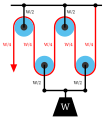
- Gyn Tackle: 5
- Threefold purchase: 6
Rope and pulley systems

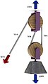
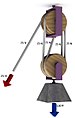
Pulley in oil derrick

A hoist using the compound pulley system yielding an advantage of 4. The single fixed pulley is installed on the hoist (device). The two movable pulleys (joined together) are attached to the hook. One end of the rope is attached to the crane frame, another to the winch.
A rope and pulley system—that is, a block and tackle—is characterised by the use of a single continuous rope to transmit a tension force around one or more pulleys to lift or move a load—the rope may be a light line or a strong cable. This system is included in the list of simple machines identified by Renaissance scientists
If the rope and pulley system does not dissipate or store energy, then its mechanical advantage is the number of parts of the rope that act on the load. This can be shown as follows.
Consider the set of pulleys that form the moving block and the parts of the rope that support this block. If there are p of these parts of the rope supporting the load W, then a force balance on the moving block shows that the tension in each of the parts of the rope must be W/p. This means the input force on the rope is T=W/p. Thus, the block and tackle reduces the input force by the factor p.
-
A gun tackle has a single pulley in both the fixed and moving blocks with two rope parts supporting the load W.
-

Separation of the pulleys in the gun tackle show the force balance that results in a rope tension of W/2.


-
A double tackle has two pulleys in both the fixed and moving blocks with four rope parts supporting the load W.
-
Separation of the pulleys in the double tackle show the force balance that results in a rope tension of W/4.


How it works
The simplest theory of operation for a pulley system assumes that the pulleys and lines are weightless, and that there is no energy loss due to friction. It is also assumed that the lines do not stretch.
In equilibrium, the forces on the moving block must sum to zero. In addition the tension in the rope must be the same for each of its parts. This means that the two parts of the rope supporting the moving block must each support half the load.
-

Fixed pulley
-

Diagram 1: The load Fon the moving pulley is balanced by the tension in two parts of the rope supporting the pulley.
-

Movable pulley
-

Diagram 2: A movable pulley lifting the load Wis supported by two rope parts with tension W/2.


These are different types of pulley systems:
- Fixed: A fixed pulley has an axle mounted in bearings attached to a supporting structure. A fixed pulley changes the direction of the force on a rope or belt that moves along its circumference. Mechanical advantage is gained by combining a fixed pulley with a movable pulley or another fixed pulley of a different diameter.
- Movable: A movable pulley has an axle in a movable block. A single movable pulley is supported by two parts of the same rope and has a mechanical advantage of two.
- Compound: A combination of fixed and a movable pulleys forms a block and tackle. A block and tackle can have several pulleys mounted on the fixed and moving axles, further increasing the mechanical advantage.
-
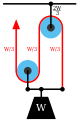
Diagram 3: The gun tackle “rove to advantage” has the rope attached to the moving pulley. The tension in the rope is W/3 yielding an advantage of three.
-

Diagram 3a: The Luff tackle adds a fixed pulley “rove to disadvantage.” The tension in the rope remains W/3 yielding an advantage of three.


The mechanical advantage of the gun tackle can be increased by interchanging the fixed and moving blocks so the rope is attached to the moving block and the rope is pulled in the direction of the lifted load. In this case the block and tackle is said to be “rove to advantage.”[9] Diagram 3 shows that now three rope parts support the load W which means the tension in the rope is W/3. Thus, the mechanical advantage is three.
By adding a pulley to the fixed block of a gun tackle the direction of the pulling force is reversed though the mechanical advantage remains the same, Diagram 3a. This is an example of the Luff tackle.
Free body diagrams
The mechanical advantage of a pulley system can be analyzed using free body diagrams which balance the tension force in the rope with the force of gravity on the load. In an ideal system, the massless and frictionless pulleys do not dissipate energy and allow for a change of direction of a rope that does not stretch or wear. In this case, a force balance on a free body that includes the load, W, and n supporting sections of a rope with tension T, yields:
- {\displaystyle nT-W=0.}

The ratio of the load to the input tension force is the mechanical advantage MA of the pulley system
- {\displaystyle MA={\frac {W}{T}}=n.}

Thus, the mechanical advantage of the system is equal to the number of sections of rope supporting the load.
Belt and pulley systems

Flat belt on a belt pulley

Belt and pulley system

Cone pulley driven from above by a line shaft
A belt and pulley system is characterised by two or more pulleys in common to a belt. This allows for mechanical power, torque, and speed to be transmitted across axles. If the pulleys are of differing diameters, a mechanical advantage is realised.
A belt drive is analogous to that of a chain drive, however a belt sheave may be smooth (devoid of discrete interlocking members as would be found on a chain sprocket, spur gear, or timing belt) so that the mechanical advantage is approximately given by the ratio of the pitch diameter of the sheaves only, not fixed exactly by the ratio of teeth as with gears and sprockets.
In the case of a drum-style pulley, without a groove or flanges, the pulley often is slightly convex to keep the flat belt centred. It is sometimes referred to as a crowned pulley. Though once widely used on factory line shafts, this type of pulley is still found driving the rotating brush in upright vacuum cleaners, in belt sanders and bandsaws.[11] Agricultural tractors built up to the early 1950s generally had a belt pulley for a flat belt (which is what Belt Pulley magazine was named after). It has been replaced by other mechanisms with more flexibility in methods of use, such as power take-off and hydraulics.
Just as the diameters of gears (and, correspondingly, their number of teeth) determine a gear ratio and thus the speed increases or reductions and the mechanical advantage that they can deliver, the diameters of pulleys determine those same factors. Cone pulleys and step pulleys (which operate on the same principle, although the names tend to be applied to flat belt versions and V belt versions, respectively) are a way to provide multiple drive ratios in a belt-and-pulley system that can be shifted as needed, just as a transmissionprovides this function with a gear train that can be shifted. V belt step pulleys are the most common way that drill presses deliver a range of spindle speeds.